Do you have a question about the Philips HTS3357/12 and is the answer not in the manual?
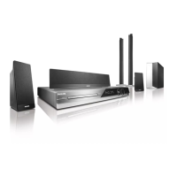
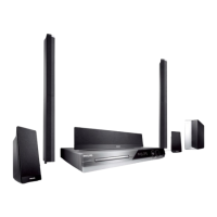
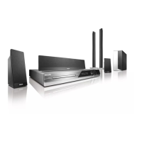
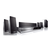
Details differences between HTS3357/05 and /12 versions.
Technical details of the audio amplifier section, including output power and frequency response.
Technical details for AM/FM radio tuning range and sensitivity.
Technical details for CD/DVD playback, including laser type and video decoding.
Power supply rating, consumption, dimensions, and weight of the main unit.
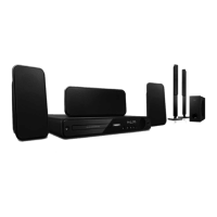
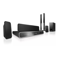
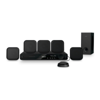
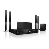
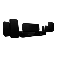
Technical details for front, rear, center, and subwoofer speakers.
List of specialized tools required for servicing the unit.
List of audio test discs for diagnostics and calibration.
Guidelines for safely mounting and dismounting chip components using proper techniques.
Measures to prevent damage from static electricity to sensitive components.
Requirements for restoring the set to its original condition and using specified parts.
Warnings related to invisible laser radiation when the unit is open.
Procedure for testing leakage current after servicing for shock hazard.
Procedures and precautions for using lead-free solder, including temperature settings.
Guidelines for using original spare parts and handling BGA-ICs.
Diagnostic flow for main unit issues starting with system and cable checks.
Diagnostic flow for main unit issues related to audio and video output problems.
Diagnostic flow for tuner and specific video output issues.
Detailed steps to safely remove the front panel assembly from the unit.
Steps for removing the main printed circuit board from the chassis.
Steps for removing the SCART board from the unit.
Visual guide and notes for component service in position A.
Visual guide and notes for component service in position B.
Overview of the SCART board's schematic and physical layout.
Detailed schematic of the SCART board connections and components.
Top-view physical layout of the SCART board components and traces.
Pinout configuration for the FTD display connected to the control board.
Specific voltage readings for integrated circuit IC251.
Specific voltage readings for transistors Q2501 and Q2502.
Top-view physical layout of the control board components.
Bottom-view physical layout of the control board components.
Detailed internal schematic for the CO4558A operational amplifier IC.
Detailed internal schematic for the V5888S servo control IC.
Detailed voltage measurements for various ICs on the main board.
Detailed voltage measurements for transistors on the main board.
Detailed voltage measurements for power supply ICs.
Detailed voltage measurements for power board transistors.
Comprehensive list of part numbers for main unit components.
Comprehensive list of part numbers for speaker system components.
| Brand | Philips |
|---|---|
| Model | HTS3357/12 |
| Category | Home Theater System |
| Language | English |