Mechanical Instructions
EN 10 LC4.2E AA4.
1. Release the two clamps (1) at the I/O panel bracket.
Carefully pull the bracket in the direction (2), as shown at
the figure “I/O panel removal”, and remove it.
2. Disconnect all cables from the I/O panel.
3. Remove all mounting screws from the I/O panel (3).
4. Take out the I/O panel.
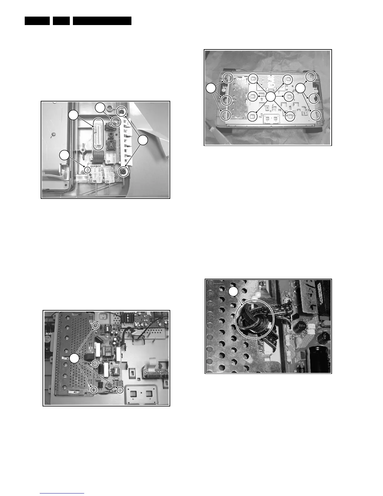
4.6 Side I/O & Keyboard Panel and Front LED
Panel Removal
Figure 4-10 Side I/O & Keyboard panel and
Front LED panel removal
1. Release the clamp (1) and take out the Front LED panel.
2. Disconnect the cable (2) from the Side I/O & Keyboard
panel.
3. Remove all mounting screws (3) from the Side I/O &
Keyboard panel bracket.
4. Unlock this unit by shifting it to the outside direction of the
monitor.
5. Release the clamp (4) and take out the Side I/O &
Keyboard panel from the bracket.
4.7 Pixel Plus Panel Removal
Figure 4-11 Pixel Plus panel removal
1. Disconnect all cables from the Pixel Plus panel.
2. Remove all mounting screws from the Pixel Plus panel.
3. Take out the Pixel Plus panel.
4.8 Exchanging the LCD Panel
Figure 4-12 Exchanging the LCD panel
1. Disconnect all cables from the LCD Panel.
2. Remove all mounting screws (1) from the metal cover.
3. Lift and take off the metal cover.
4. Now you can exchange the LCD panel.
4.9 Re-Assembly
To re-assemble the whole set, do all processes in reverse
order.
Notes:
• Do not forget to replace the ground cable of the TV &
Scaler board, while mounting the screw at the board
topside. See figure “TV & Scaler board removal”.
• Make sure the ferrite ring (1) is properly tightened to the clip
(this is valid only for 26 inch sets).
Figure 4-13 Ferrite ring
E_14490_009.eps
130404
3
1
2
4
E_14520_005.eps
100204
1
E_14490_010.eps
130404
1
1
1
E_14490_055.eps
070504
1