Service Modes, Error Codes, and Fault Finding
EN 16 LC4.2E AA5.
If possible, check the entire contents of the error buffer. In
some situations, an error code is only the result of another error
and not the actual cause of the problem (for example, a fault in
the protection detection circuitry can also lead to a protection).
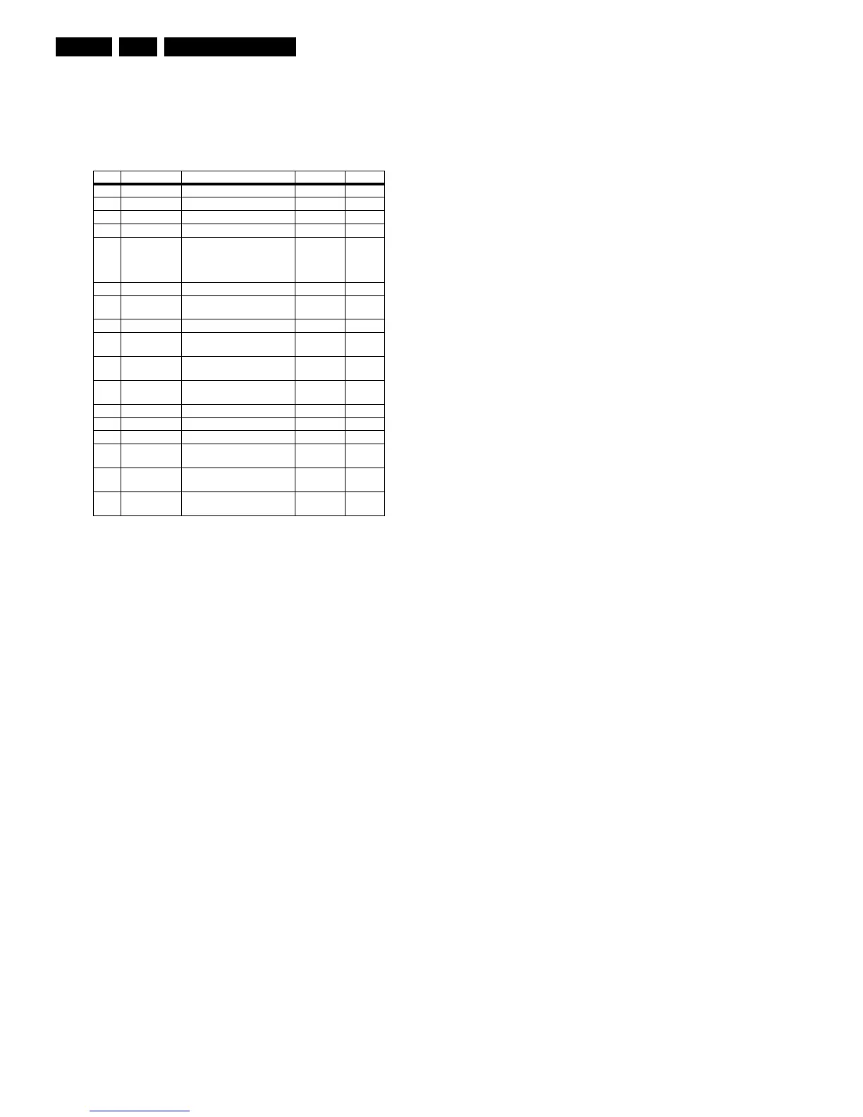
Table 5-1 Error code overview
5.6 The Blinking LED Procedure
Using this procedure, you can make the contents of the error
buffer visible via the front LED. This is especially useful when
there is no picture.
When the SDM is entered, the front LED will blink the contents
of the error-buffer:
• The Led blinks with as many pulses as the error code
number, followed by a time period of 1.5 seconds, in which
the Led is off.
• Then this sequence starts is repeated.
Any RC5 command terminates this sequence.
Example of error buffer: 12 9 6 0 0
After entering SDM, the following occurs:
• 1 long blink of 5 seconds to start the sequence,
• 12 short blinks followed by a pause of 1.5 seconds,
• 9 short blinks followed by a pause of 1.5 seconds,
• 6 short blinks followed by a pause of 1.5 seconds,
• 1 long blink of 1.5 seconds to finish the sequence,
• The sequence starts again at 12 short blinks.
5.7 Fault Finding and Repair Tips
Notes:
• It is assumed that the components are mounted correctly
with correct values and no bad solder joints.
• Before any fault finding actions, check if the correct options
are set.
5.7.1 NVM Editor
In some cases, it can be handy if one directly can change the
NVM contents. This can be done with the “NVM Editor” in SAM
mode.
5.7.2 Load default NVM values
In case a blank NVM is placed or when the NVM content is
corrupted, default values can be downloaded into the NVM.
After the default values are downloaded it will be possible to
start up and to start aligning the TV set. This is no longer
initiated automatically; to initiate the download the following
action has to be performed:
1. Switch off the TV set via the mains switch
2. Short circuit the SDM jumpers (keep short circuited)
3. Press P+ or Ch+ on the local keyboard (and keep it
pressed)
4. Switch on the TV set via the mains switch
5. When the set has started up the P+/Ch+ button can be
released and the short circuit of the SDM jumpers can be
removed.
6. The red LED will be on continuously to indicate that the
download is initiated (normally when SDM is activated the
red LED will start with the Blinking LED sequence).
7. Wait +/- 30 Seconds (time needed to download default
values to the NVM)
Result: The set is in SDM, the NVM is loaded with default
values and the blinking LED is not activated (The blinking LED
is not activated in this case to show that the download has been
performed), the LED will be on.
5.7.3 Tuner and IF
No Picture in RF mode
1. Check whether picture is present in AV. If not, go to Video
processing troubleshooting section.
2. If present, check that the Option settings are correct.
3. Check that all supply voltages are present.
4. Check if I2C lines are working correctly (3.3V).
5. Manually store a known channel and check if there is IF
output at Tuner pin 11.
6. Feed in 105 dBuV at Tuner pin 11 and check whether there
is RGB output from Video Processing IC. If yes, Tuner may
be defected. Change Tuner.
Sound in picture problem for L' system (rolling horizontal
lines)
1. Check whether AGC L' in Sam mode is set to 0.
2. If yes, align the set to correct value.
Required system is not selected correctly
1. Check whether the Service jumper (#4022, 08 05 size) is
present. If yes, remove it.
2. Check whether SEL_IF pin is according to what is
specified.
Error Device Error description Check item Diagram
0 Not applicable No Error
1 Not applicable - - -
2 Not applicable - - -
3 Not applicable - - -
4 GM1501 I2C error while communicating
with the Genesis Scaler
and/or Flash-ROM is faulty/
empty
7401
7530
A7A11
5 Not applicable +5v protection 7930 A6
6 I2C bus General I2C error 7011, 3088,
3096
A2
7 Not applicable - - -
8 M24C32 I2C error while communicating
with the Scaler EEPROM
7531 A11
9 M24C16 I2C error while communicating
with the EEPROM
7099 A2
10 Tuner I2C error while communicating
with the PLL tuner
1302, 3302,
3303, 3327
A1
11 Not applicable - - -
12 Not applicable - - -
13 Not applicable - - -
14 K4D263238M Read-write error with the
Scaler SDRAM
7501 A10
15 TDA9178T/N1 I2C error while communicating
with Histogram
7560 A3
16 EPIC12F I2C error while communicating
with EPLD on Pixel Plus panel
7101 PP1