Circuit Descriptions, Abbreviation List, and IC Data Sheets
EN 71LC4.2E AA 9.
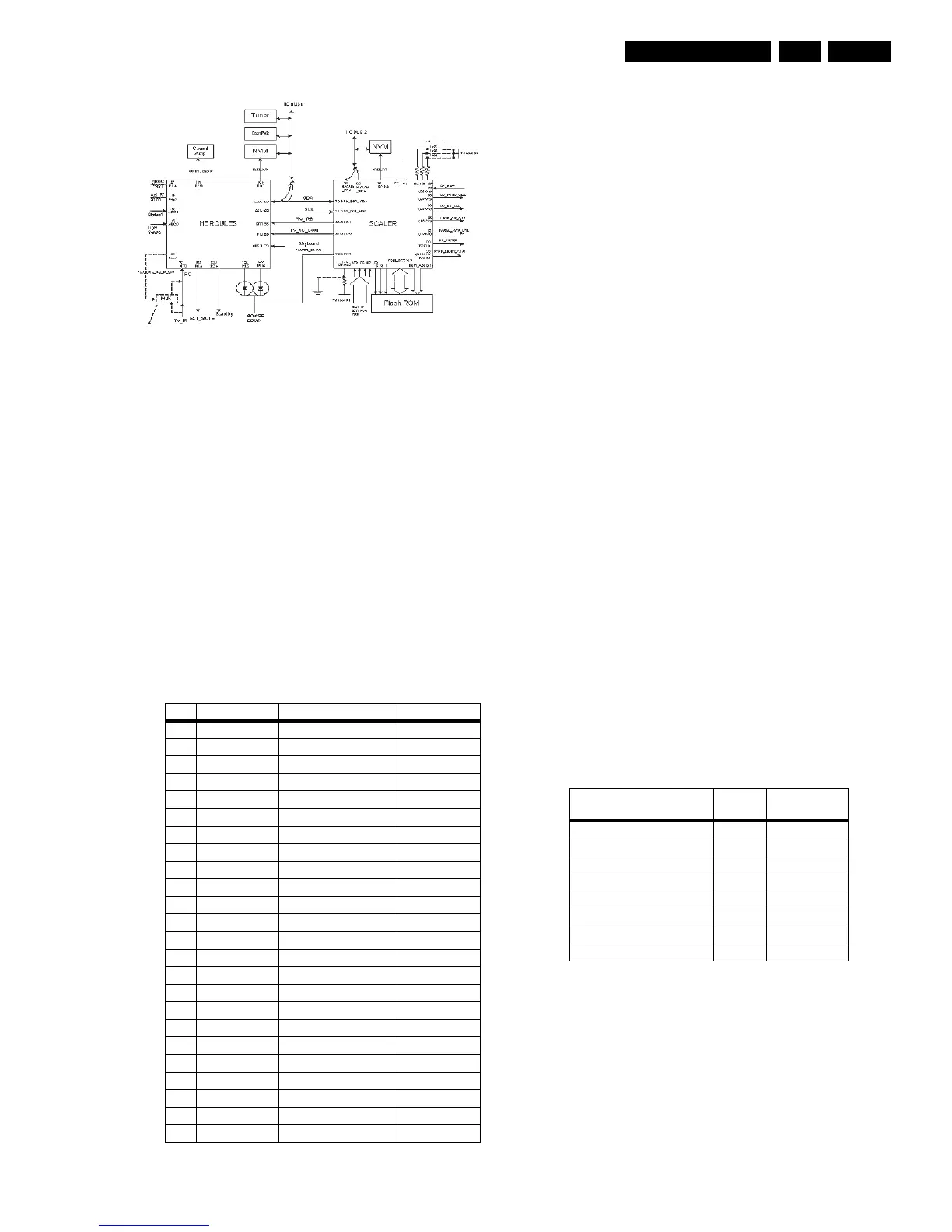
Figure 9-5 Micro Controller block diagram
9.10.3 Basic Specification
The Micro Controller operates at the following supply voltages:
• +3.3 V_dc at pins 4, 88, 94, and 109.
• +1.8 V_dc at pins 93, 96, and 117.
• I2C pull up supply: +3.3V_dc.
9.10.4 Pin Configuration and Functionality
The ports of the Micro Controller can be configured as follows:
• A normal input port.
• An input ADC port.
• An output Open Drain port.
• An output Push-Pull port.
• An output PWM port.
• Input/Output Port
The following table shows the ports used for the L04 control:
Table 9-2 Micro Controller ports overview
The description of each functional pin is explained below:
• LED. This signal is used as an indication for the Standby,
Remote and Error Indicator. Region diversity:
– During protection mode, the LED blinks and the set is
in standby mode.
– During error conditions it blinks at a predefined rate.
– After receiving a valid RC-5 or local keyboard
command it flashes once.
– For sets with error message indication, the LED blinks
when message is active and the set is in standby
mode.
• SCL. This is the clock wire of the two-wire single master bi-
directional I2C bus.
• SDA. This is the data wire of the two-wire single master bi-
directional I2C bus.
• STANDBY. The Hercules generates this signal. This can
enable the power supply in normal operation and disable it
during Standby. It is of logic “high” (3.3 V) under normal
operation and “low” (0 V) during Standby.
• IR. This input pin is connected to an RC5 remote control
receiver.
• SEL-IF. This is an output pin to switch the Video SAW filter
between M system and other systems.
– 0: NTSC M (default)
– 1: PAL B/G, DK, I, L
• NVM_WP. The global protection line is used to enable and
disable write protection to the NVM. When write to the
NVM is required, pin 7 of the NVM must be pulled to logic
‘0’ first (via Write_Protect of the micro-controller pin) before
a write is performed. Otherwise pin 7 of NVM must always
be at logic “1”
– 0: Disabled
– 1: Enabled (default)
• SOUND_ENABLE. This pin is use to MUTE the audio
amplifier. It is configured as push pull.
• STATUS_1. This signal is used to read the status of the
SCART 1 input.
• STATUS_2. This signal is used to read the status of the
SCART 2 input.
• HERC_RESET. This pin is use to switch the +1.8V supply.
• POWER_DOWN. The power supply generates this signal.
Logic “high” (3.3 V) under normal operation of the TV and
goes “low” (0 V) when the Mains input voltage supply goes
below 70 V_ac.
• Keyboard. Following are the Keyboard functions and the
step values (8 bit) for it.
Table 9-3 Local keyboard values
• TV_IRQ. This signal is the interrupt from the Scaler IC.
• TV_SC_COM. This signal is used for the communication
with the Scaler IC.
• EXT_MUTE. This signal is used to reduce the Switch-off
plop.
9.11 LCD Display
9.11.1 Specifications
Panel model : LC171W03-A4K3
(17”)
Pin Name Description Configuration
97 INT0/ P0.5 IR INT0
98 P1.0/ INT1 TV_IRQ INT2
99 P1.1/ T0 TV_SC_COM P1.1
102 P0.4/ I2SWS EXT_MUTE P0.4
103 P0.3/ I2SCLK Lip Sync I2SCLK
104 P0.2/ I2SDO2 NVM_WP P0.2
105 P0.1/ I2SDO1 Lip Sync I2SDO1
106 P0.0/ I2SDI/O Lip Sync I2SDI/O
107 P1.3/ T1 PC-TV_LED P1.3
108 P1.6/ SCL SCL SCL
109 P1.7/ SDA SDA SDA
111 P2.0/ TPWM SOUND_ENABLE P2.0
112 P2.1/ PWM0 (for future use) -
113 P2.2/ PWM1 (for future use) -
114 P2.3/ PWM2 SEL_IF P2.3
115 P3.0/ ADC0 Light Sensor - SDM ADC0
116 P3.1/ ADC1 STATUS_1 ADC1
119 P3.2/ ADC2 STATUS_2 ADC2
120 P3.3/ ADC3 KEYBOARD ADC3
122 P2.4/ PWM3 STANDBY P2.4
123 P2.5/ PWM4 (for future use) -
126 P1.2/ INT2 (for future use) -
127 P1.4/ RX HERC_RESET -
128 P1.5/ TX POWER_DOWN P1.5
E_14490_062.eps
020604
Function Voltage
(V_dc)
Step values
(8 bit)
NAFTA Standby 0 0 - 6
Ch + 0.43 7 - 33
Exit Factory (Ch- and Vol-) 0.69 34 - 53
Ch - 0.93 54 - 73
Menu (Vol - and Vol +) 1.19 74 - 96
Vol - 1.49 97 - 121
DVD Eject 1.8 122 - 147
Vol + 2.12 148 - 169