Mechanical Instructions
EN 14 LC7.1HE LA4.
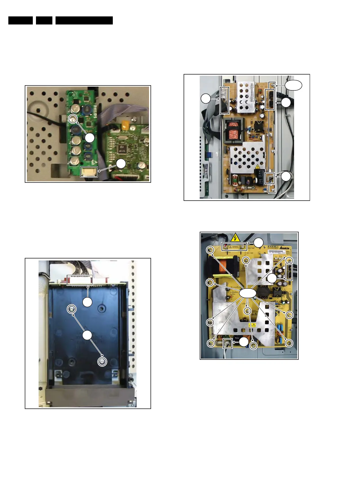
4.3.7 DC-DC converter for i-Board (26" optional)
1. Remove the rear cover, as described earlier.
2. Refer to fig. “DC-DC converter for i-Board removal” below.
3. Disconnect the cable [1] on the DC-DC converter for
i-Board.
4. Remove the screw [2] that hold the panel.
5. Lift the i-Board from the set.
Figure 4-12 DC-DC converter for i-Board removal
4.3.8 Smart Card Interface (optional)
1. Remove the rear cover, as described earlier.
2. Refer to fig. “Smart Card Interface removal” below.
3. Disconnect all cables [1] on the Smart Card Interface.
4. Remove the screws [2] that hold the Smart Card Interface.
5. Lift the Smart Card Interface from the set.
Figure 4-13 Smart Card Interface removal
4.3.9 Main Supply Panel
1. Refer to next figures.
2. Unplug cables [a].
3. Remove the fixation screws [b].
4. Take the board out (it hinges at the left side).
Figure 4-14 Main supply panel 26" and 32".
Figure 4-15 Main supply panel 42".
H_17150_117.ep
16080
1
2
H_17150_111.ep
14080
1
2
G_16860_065.ep
a
a
a
b (3×)
H_16940_016.eps
310707
a
a
a
b (10×)
 Loading...


