Technical Specifications, Connections, and Chassis Overview
EN 3LC7.1HE LA 1.
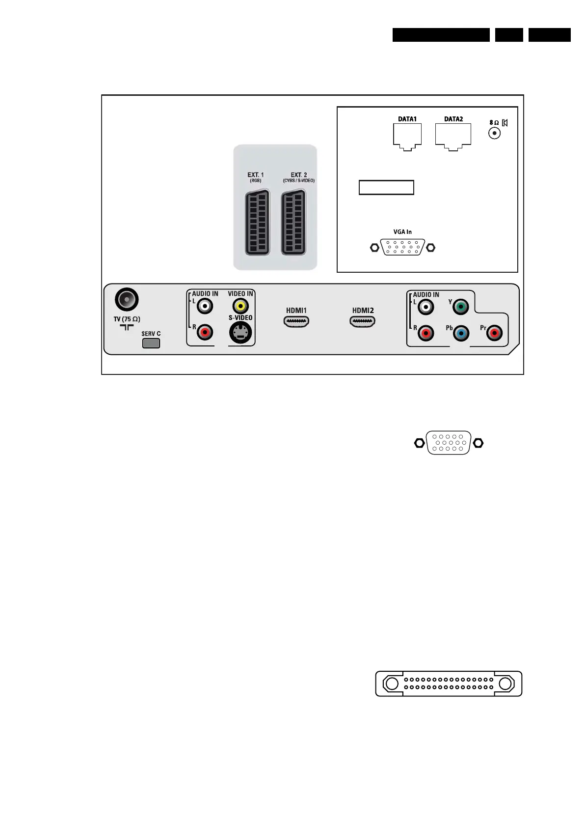
1.2 Connection Overview
Figure 1-1 Rear I/O connections
Note: The following connector colour abbreviations are used
(acc. to DIN/IEC 757): Bk= Black, Bu= Blue, Gn= Green, Gy=
Grey, Rd= Red, Wh= White, and Ye= Yellow.
1.2.1 Rear Connections (top)
RJ12 DATA1 (HM-Link - In/Out)
1 - LED_in < 0.3 V, active low j
2 - IR_in < 0.3 V, active low j
3 - MODE Vcc j
4 - TV Power Status 4.5 to 5 V: TV “On”
< 0.3 V: TV “Stdby”
High impedance: TV “Off” k
5 - Gnd Gnd H
6 - IR_out Signal k
RJ45 DATA2 (Xpress Box - In/Out)
1-+12 V +12V/1W k
2 - Gnd Gnd H
3 - H-sync Signal k
4 - V-sync Signal k
5 - TXD232 Signal
6 - RXD232 Signal
7 - SDA3_IR-OUT Signal k
8 - DCM-POR Signal k
9 - CVBSterr Signal k
10 - Gnd CVBSterr Gnd H
Mini Jack: Speaker - Out
- Loudspeaker 8 ohm ok
VGA: Video RGB - In
Figure 1-2 VGA Connector
1 - Video Red 0.7 V
PP
/ 75 ohm j
2 - Video Green 0.7 V
PP
/ 75 ohm j
3 - Video Blue 0.7 V
PP
/ 75 ohm j
4-n.c.
5 - Ground Gnd H
6 - Ground Red Gnd H
7 - Ground Green Gnd H
8 - Ground Blue Gnd H
9-+5V
DC
+5 V j
10 - Ground Sync Gnd H
11 - n.c.
12 - DDC_SDA DDC data j
13 - H-sync 0 - 5 V j
14 - V-sync 0 - 5 V j
15 - DDC_SCL DDC clock j
Smart-card Interface: Data Video - In/Out (optional)
Figure 1-3 Smart-card Connector
1 - 3V3 +3.3 V k
2 - Ground power Gnd H
3 - 12V +12 V j
4 - Ground I
2
C Gnd H
5 - IR data Data j
RJ12
RJ45
Special tool needed
(order via BDS)
RJ12
RJ45
Special tool needed
(order via BDS)
RJ12
RJ45
Special tool needed
(order via BDS)
RJ12
RJ45
Special tool needed
(order via BDS)
H_17510_121.eps
170807
AV
CVI
1
6
10
11
5
15
E_06532_002.eps
050404
1
17
16
32
E_06532_044.eps
130807
 Loading...


