The analog part of the Combi Board can be repaired without
opening the metal shielding box. In case of a ‘Class D’
problem it is advised to disassemble the board first,
desolder the metal bottom of the shielding box and
assemble the board again. This takes a few minutes only.
Attention: Poor soldering of the metal shielding box results
in disturbance of the tuner.
In most cases the FETs 7109 and/or 7121 for the left
channel, respectively 7218 and/or 7231 for the right channel
will be defective. This can be checked easily with an
ordinary Ohm-meter.
LEFT CHANNEL:
In case 7109 is defect replace following parts:
7109, 7111, 7105, 7119, 7104, 3101, 3103 and 2106
In case 7121 is defect replace following parts:
7121, 7113, 7118, 7117,3129, 3130 and 2118
RIGHT CHANNEL:
In case 7218 is defect replace following parts:
7218, 7221, 7209, 7228, 7208, 3205, 3209 and 2206
In case 7231 is defect replace following parts:
7231, 7210, 7235, 7227, 3241, 3243 and 2220
If none of the FETs is defective the fault is most probably
located in the modulator. To check the operation - follow the
given signals.
General description of Oscilloscope setup:
The following signals are measured on condition:
AUX in = 500mV/1kHz, Volume = -28dB
Load = 2 x 6Ω
Measuring point
A can be found on circuit diagram 3.
All other measuring points are shown on circiut diagram
4
respectively 5.
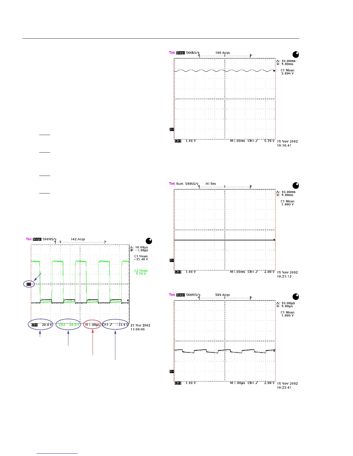
Measuring point A: Output pre-amplifier
Normal analog signal measured (1kHz- Timebase 1µs). If
this signal can´t be measured - the fault is outside the
shielding box.
Measuring point B: Input Modulator
The 1kHz signal not visible anymore. Reducing the
timebase to 1µs shows the oscillogram below.