Do you have a question about the Philips MC-M570/21 and is the answer not in the manual?
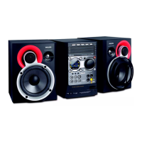
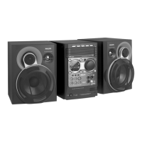
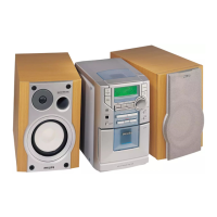
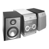
General technical parameters of the micro system.
FM and MW tuner specifications.
Output power and specifications for the amplifier.
Specifications for the 5DTC module, including output voltage.
USB interface specifications.
Steps to dismantle the 5DTC module.
Instructions to detach the front panel assembly.
Steps to dismantle the front panel assembly.
Steps to dismantle the rear panel assembly.
Service hints and recommended positions for repair.
Procedure for testing the tuner section.
Test for 5DTC and MP3 module.
Test for Analog-to-Digital Converter inputs.
Test for EEPROM data integrity.
Formatting the EEPROM with default data.
Test for the rotary encoder function.
Notes on main signal path measurements and conditions.
Explanation of symbols and abbreviations used in the diagram.
Pin connection details for the FTD display.
Table showing component variants for different models.
List of electrical components for the front board.
Notes on DC voltage measurements at different modes.
Notes on DC voltage measurements at different modes.
Component layout of the CDC key board.
Table showing component variants for different models.
Circuit diagram of the CDC key board.
List of miscellaneous parts for the front board.
List of capacitors for the front board.
List of resistors for the front board.
Continuation of the resistor list for the front board.
Continuation of the resistor list for the front board.
List of coils and filters for the front board.
List of diodes for the front board.
List of transistors and ICs for the front board.
Block diagram of the ECO6 tuner board.
Schematic diagram of the ECO6 tuner board.
Component layout of the ECO6 tuner board.
Adjustment table for the ECO6 tuner board.
Electrical parts list for the ECO6 tuner board.
Explanation of symbols used in the tuner board schematic.
Components related to version programming.
Details on version detection components.
Tuning adjustments for the varicap.
Adjustment for FM Intermediate Frequency.
Adjustment for FM Voltage Controlled Oscillator.
Adjustment for FM RF channel separation.
Adjustment for AM Intermediate Frequency.
Adjustment for AM Automatic Frequency Control.
Adjustment for AM Radio Frequency.
Adjustment for Long Wave tuning.
Adjustment for Medium Wave tuning.
List of miscellaneous parts for the ECO6 tuner board.
List of capacitors for the ECO6 tuner board.
List of resistors for the ECO6 tuner board.
Block diagram of the ECO6 Cenelec tuner board.
Schematic diagram of the ECO6 Cenelec tuner board.
Component layout of the ECO6 Cenelec tuner board.
Adjustment table for the ECO6 Cenelec tuner board.
Electrical parts list for the ECO6 Cenelec tuner board.
Explanation of symbols used in the tuner board schematic.
Components related to version programming.
Details on version detection components.
Tuning adjustments for the varicap.
Adjustment for FM RF channel separation.
FM tuning adjustments.
Adjustment for AM Intermediate Frequency.
Adjustment for AM Automatic Frequency Control.
Adjustment for AM Radio Frequency.
Adjustment for Long Wave tuning.
Adjustment for Medium Wave tuning.
List of miscellaneous parts for the ECO6 tuner board.
List of capacitors for the ECO6 tuner board.
List of resistors for the ECO6 tuner board.
Checking the playability and complaint verification.
Procedure for cleaning the CD drive lens.
Measuring the eye-pattern signal for jitter.
Measuring the laser current of the CD drive.
Measuring CD drive photodiode offsets.
Measuring offsets of the CD10 signal processor.
Steps for replacing the CD drive mechanism.
Block diagram of the CD mechanism.
Block diagram of the CD mainboard.
Block diagram of the MP3 board.
Block diagram of the motor board.
Block diagram of the control board.
Mapping of components to the circuit diagram.
Mapping of components to the layout.
Exploded view sketch 1 of the 5DTC mechanic.
Exploded view sketch 2 of the 5DTC mechanic.
List of mechanical parts for the CD board.
List of miscellaneous parts for the CD board.
List of capacitors for the CD board.
List of resistors for the CD board.
List of resistors for the CD board.
List of coils and diodes for the CD board.
List of transistors for the CD board.
List of integrated circuits for the CD board.
List of mechanical parts for the control board.
List of miscellaneous parts for the control board.
List of capacitors for the control board.
List of resistors for the control board.
List of misc. parts and capacitors for the MP3 board.
List of resistors for the MP3 board.
List of coils and diodes for the MP3 board.
List of transistors for the MP3 board.
List of integrated circuits for the MP3 board.
Overview of the Class D amplifier's circuit.
Troubleshooting and service tips for the module.
Circuit diagram of the Combi board.
Component layout of the Combi board.
Component layout of the Mains board.
Circuit diagram of the Mains board.
Parts list for the Mains board.
Details on oscillator, modulator, FET drivers, and output filter.
Description of amplifier protection circuits.
Output pre-amplifier signal measurement.
Input modulator signal measurement.
General oscilloscope setup description.
Measurements of triangle waveforms.
Output modulator signal measurement.
Modulator frequency measurement.
FET gate signal measurement.
Digital output signal measurement.
Output filter signal measurement.
Audio signal restoration measurement.
Overview of the source selector part.
Overview of oscillator and pre-amplifier parts.
Overview of the left channel amplifier part.
Overview of the right channel amplifier part.
Overview of audio frequency and logic parts.
Circuit diagram of the source selector part.
Circuit diagram of audio frequency and logic parts.
Circuit diagram of supply, oscillator, and pre-amp.
Circuit diagram of the left channel amplifier.
Circuit diagram of the right channel amplifier.
List of misc. parts and capacitors for the mains board.
List of coils and diodes for the mains board.
List of transistors for the mains board.
List of resistors for the mains board.
List of mechanical parts for the Combi board.
List of miscellaneous parts for the Combi board.
List of capacitors for the Combi board.
List of resistors for the Combi board.
Continuation of resistor list for the Combi board.
Continuation of resistor list for the Combi board.
List of resistors for the Combi board.
List of coils and diodes for the Combi board.
List of transistors for the Combi board.
Continuation of transistor list for the Combi board.
List of integrated circuits for the Combi board.
| Type | Micro Hi-Fi System |
|---|---|
| Audio Formats Supported | MP3 |
| Radio Tuner | FM |
| Bluetooth | No |
| Speaker Type | 2-way |
| Disc Playback | CD |
| Connectivity | Aux-in, Headphone out |
| Presets | 20 FM |