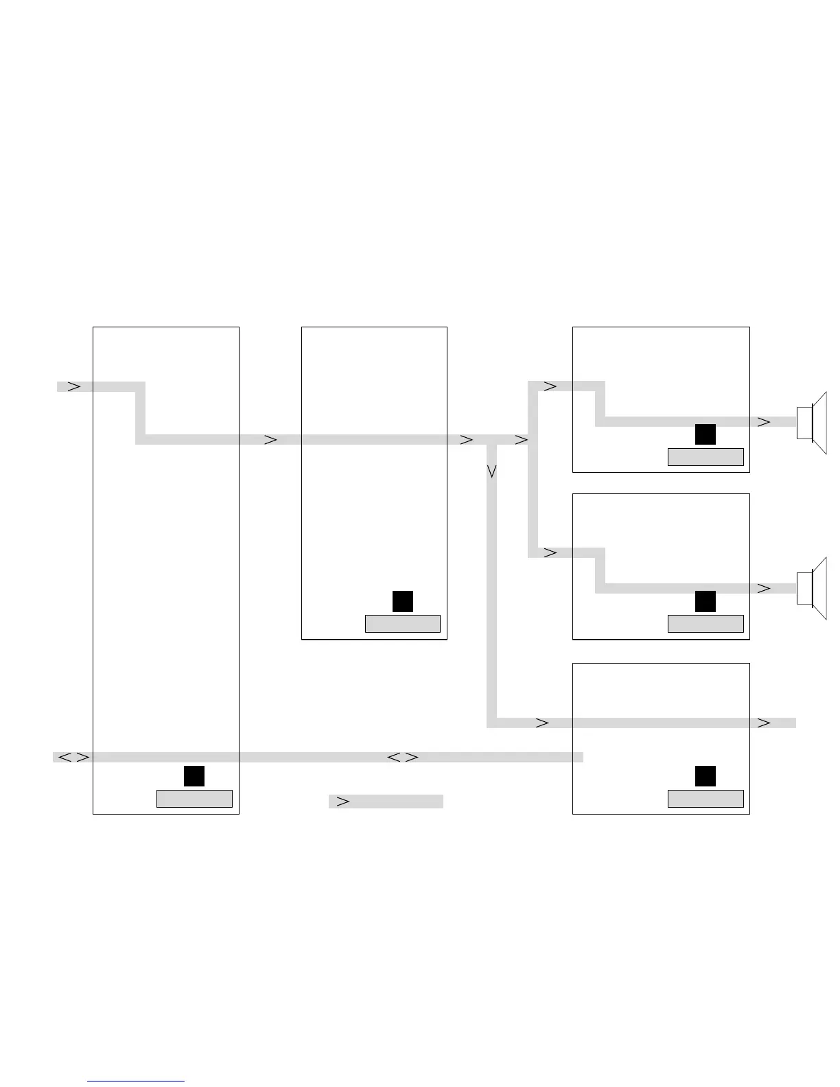
SOURCE SELECTOR PART OSCILLATOR & PRE-AMPLIFIER PART AMPLIFIER PART LEFT CHANNEL
AMPLIFIER PART RIGHT CHANNEL
AUDIO FREQUENCY & LOGIC PART
Inputs:
AUX
Tape / USB
Tuner
CD
Source Selector IC + sound processing
Data generation for spectrum analyzer
Digital Out (provisional only)
Overvoltage protection for:
+AMP
-AMP
+5V6
+12V_A
Control Lines
Generation of following supplies:
+12V
+5V6
+5V_AMP
Pre-Amplifier + mute circuit
Adjustment of offset
Square wave Oscillator
Headphone Amplifier
Subwoofer out (provisional only)
Port Expander (shift register)
Generation of +5V_CD
Fan control
Modulator
Driver + Level shifter
Power FETs
Protection circuits
Modulator
Driver + Level shifter
Power FETs
Protection circuits
Speaker relay
p
Chapter 11-8
Signal flow
Chapter 11-10
Chapter 11-11
Chapter 11-12
Chapter 11-9
Power 2003 100W Class D
Combi Board Circuit Diagram Overview
P2003 Class D Drawing Overview 2002 12 17
1 2
3
4
5