Do you have a question about the Philips MC230 and is the answer not in the manual?
Details specific features and boards used across different model versions.
Covers mains voltage, frequency, clock accuracy, and unit dimensions.
Lists tuning range, sensitivity, selectivity, and distortion for FM and MW.
Details output power, frequency response, and sound controls like DSC and DBB.
Outlines the test equipment and procedure for FM tuner measurements.
Details the test setup and conditions for AM tuner measurements.
Describes test equipment and methods for CD and tape recorder performance checks.
Lists required tools, testers, and electrostatic discharge (ESD) protection equipment.
Identifies necessary test cassettes and discs for functional checks.
Provides general guidelines for handling and attaching chip components to PCBs.
Illustrates methods for removing and installing chip components safely.
Shows correct and incorrect soldering techniques for reliable repairs.
Explains sensitivity of components to electrostatic discharge and protective measures.
Warns about invisible laser radiation and avoiding direct exposure.
States requirements for restoring the set to original condition and using specified parts.
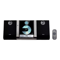
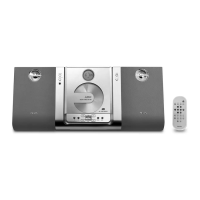
Instructions for preparing the remote control for use.
Guides on connecting speakers and antenna systems for optimal performance.
Covers connecting external equipment and replacing the remote battery.
Describes the function of buttons and indicators on the main unit.
Explains the various functions accessible via the remote control.
Details UK mains plug fuse replacement, wiring, and copyright considerations.
Includes Italian conformity, Norwegian safety, general cautions, and Finnish warnings.
Addresses issues with CD playback and radio reception quality.
Covers system unresponsiveness, audio issues, and remote control malfunctions.
Step-by-step guide to removing the rear cabinet and related parts.
Instructions for removing front panels, main board, and CD door assembly.
Provides crucial advice on handling fragile flex cables and service orientations.
Explains how to enter service test modes and displays ROM version.
Details tests for CD mechanism operations and remote control key functions.
Covers EEPROM clearing and display segment/LED checks.
Shows the physical arrangement of components on the power board's component side.
Illustrates the layout of Surface Mount Devices (SMD) on the power board.
Shows the physical arrangement of components on the Key_A board's component side.
Illustrates the layout of SMD components on the Key_A board.
Shows the physical arrangement of components on the Key_B board's component side.
Illustrates the layout of SMD components on the Key_B board.
Displays the physical arrangement of components on the Key_C board's component side.
Illustrates the layout of SMD components on the Key_C board.
Shows the physical arrangement of components on the main PCB's component side.
Displays further component placement details on the main PCB's component side.
Shows the top layout for the headphone connection PCB.
Shows the bottom layout for the headphone connection PCB.
Displays the physical arrangement of components on the display board's component side.
Illustrates the layout of SMD components on the display board.
Lists part numbers and descriptions for mechanical and accessory items.
Lists part numbers and descriptions for electronic components and integrated circuits.
| Display type | LCD |
|---|---|
| Backlight color | Blue |
| Type | Home audio micro system |
| Cassette deck | No |
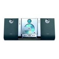
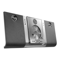
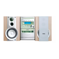
| Product color | Silver |
| Disc loading type | Front |
| Optical disc player | Yes |
| Number of optical discs | 1 discs |
| Speaker type | 2-way |
| RMS rated power | 20 W |
| Woofer diameter | 76.2 mm |
| Number of speakers | - |
| Supported radio bands | FM, MW |
| Preset stations quantity | 40 |
| Apple docking compatibility | Not supported |
| Storage media type | Not available |
| Headphone outputs | 1 |
| Headphone connectivity | 3.5 mm |
| Playback modes | Program, Repeat, Repeat all, Repeat one, Shuffle |
| Disc types supported | CD, CD-R, CD-RW |
| Power source | AC |
| Depth | 96 mm |
|---|---|
| Width | 250 mm |
| Height | 245 mm |
| Package depth | 375 mm |
| Package width | 305 mm |
| Package height | 314 mm |
| Package weight | 5600 g |
| Main speaker width | 166 mm |