Mechanical Instructions
EN 13DVDR615, MRV640 4.
4.2 Dismantling Instructions
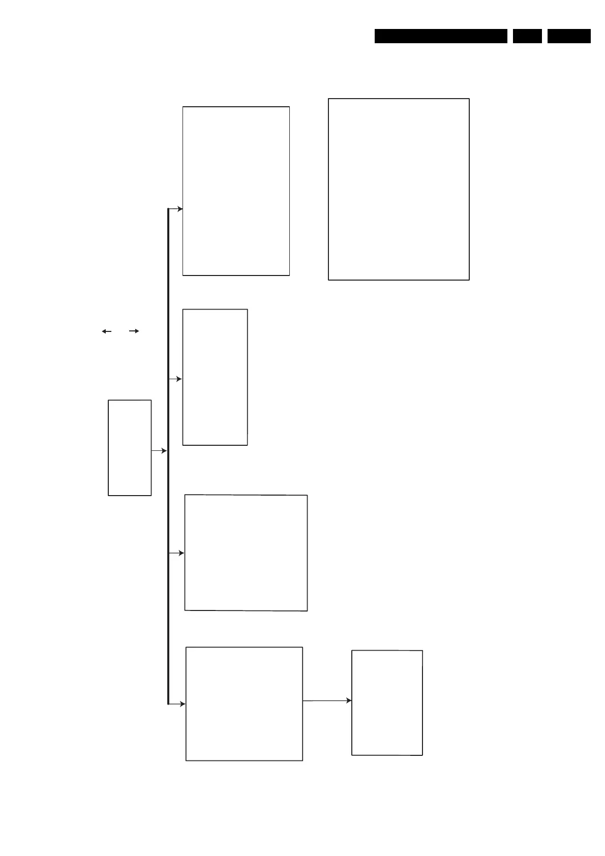
Figure 4-7
DISMANTLING INSTRUCTIONS
See exploded view for item numbers
Front assy
⇒
⇒
remove 3 screws 188
(front assy
→
frame 224)
⇒
unlock the front from the
frame by releasing 2 snaps
on left and right
mounting
demounting
Cover 196
⇒
Remove 9 screws 298
⇒
Lift the cover
Analog board 1021
⇒
⇒
demount the board
remove screw safety
holder 226
DVDR BASIC ENGINE 1024
Manual opening of tray and removal of
In case the loader is defective and cannot be
opened electrically, you can open the tray
as follows:
⇒
⇒
Open the tray and remove
the tray front 134 + 138
⇒
Remove the connections
⇒ Remove the connections
Display board 1023
⇒
⇒
Remove 4 screws 177
→
demount the board
open the tray and remove
tray front 134 + 138
Remove 4 screws 260
(assembly -> frame 224)
(board
front)
→
demount the board.
Digital board 1022
⇒
⇒
Remove 4 screws 273
(Digital board frame 224)
to remove
the
Open the unlocked tray.
It is possible to unlock the tray by means
of a screwdriver via a slot in the
front and frame at the underside.
.
⇒
⇒
Push the white pin of the slider at the
underside of the basic engine to the left
(seen from the front)
⇒ remove 4 screws 296, 298
(board frame)
→
⇒ remove 12 screws 247, 255
(board backplate)
⇒
Remove the connections
→
⇒ remove 3 screws 232
(frame backplate)
→
tray front 134 + 138
⇒
remove 4 screws 186 to
remove the plate front 184
⇒
Remove screws 172
of DV input cable
TR 06003_002
100304
Remove 2 screws 262
(assembly -> support bracket 256)
Uncatch dust cover assembly 147 + 148
from DVDR Basic Engine
⇒
⇒