Mechanical Instructions
EN 12 DVDR615, MRV6404.
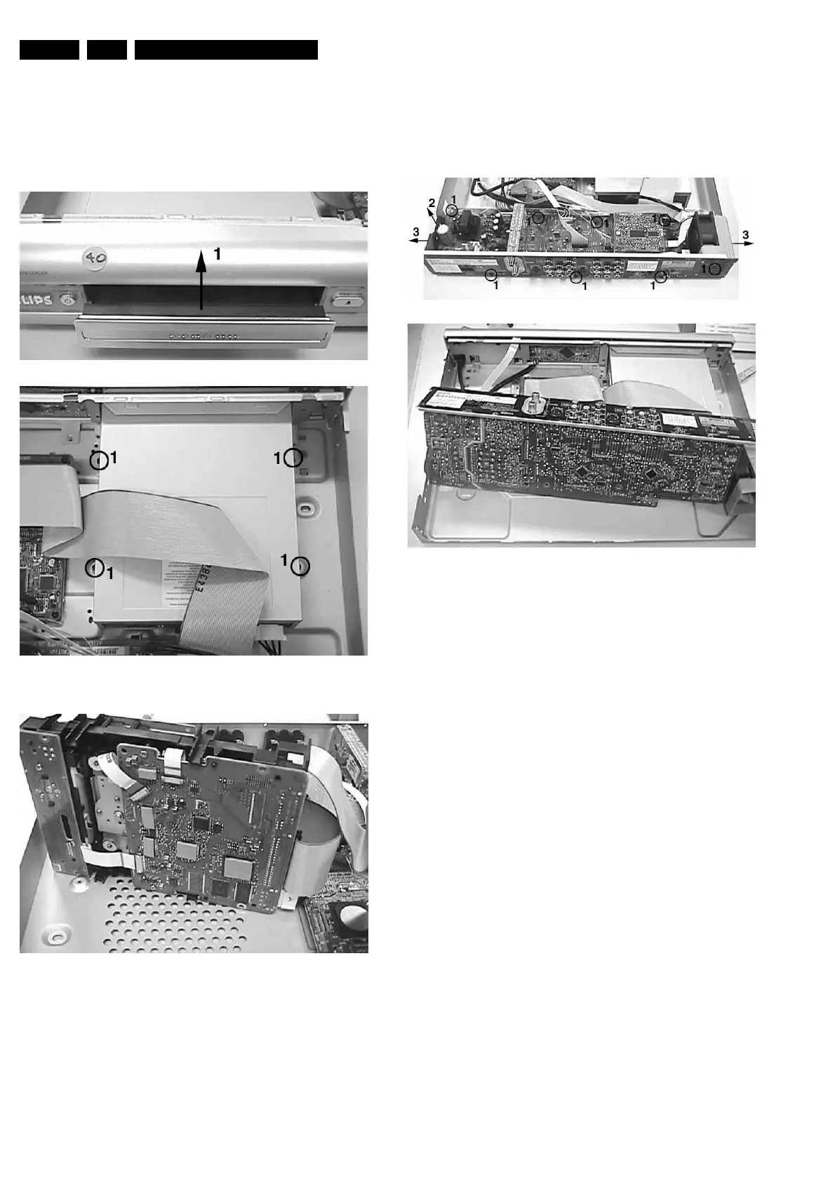
4.1.3 Basic Engine
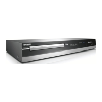
– Remove the tray 134 + 138
– Remove the 6 screws 260, 262
– Remove 4 screws to remove the Basic Engine metal
casing.
– Place the engine in the service position
Figure 4-4
Figure 4-5
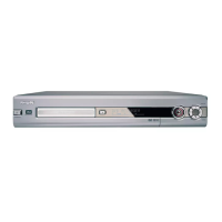
4.1.4 Analog Board
– Remove the 8 screws 232, 296 and 298
– Remove screw safety holder 226
– Unlock the two snaps hooks on the left and right
– Turn the PCB in the service position
Figure 4-6