Directions For Use
EN 9DVDR615, MRV640 3.
Quick install guide
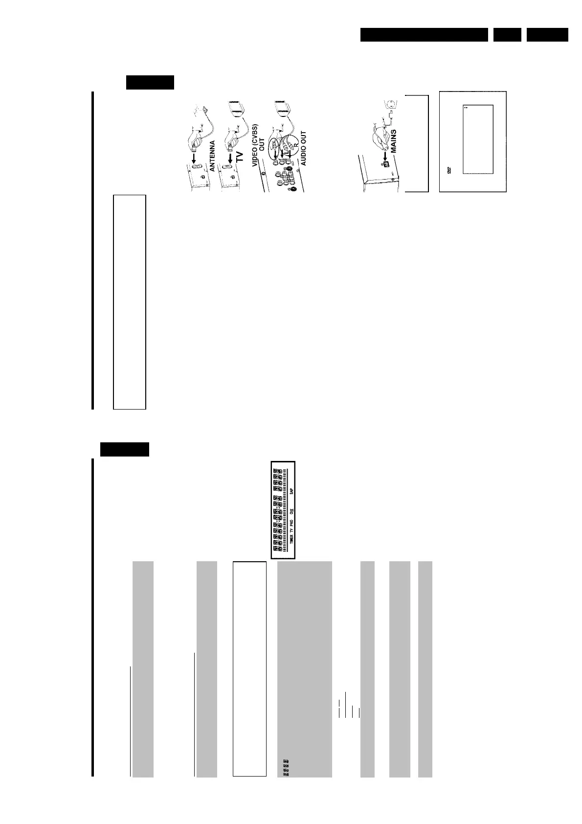
Connecting your DVD recorder to the TV
set/Initial installation
Attention ! Until the initial installation has been completed, the buttons on the front
will not function.
1
Remove the antenna or cable TV signal from your TV. Connect it
to the ANTENNA IN jack at the back of the DVD recorder.
2
Insert one end of the supplied antenna cable into the TV
OUT jack at the back of the DVD Recorder and the other end
into the antenna input jack at the back of the TV.
3
Use the supplied video (CVBS) cable and plug one end into the
yellow jack OUT VIDEO (CVBS) at the back of the DVD
Recorder and the other end into the Video In jack (usually
yellow) of the TV (usually called Video in or AV in. See your TV's
instruction manual).
4
Use the supplied audio (cinch) cable and plug one end into the
red/white cinch jack OUT L AUDIO R at the back of the DVD
Recorder (under to Video in ) and the other into the
corresponding red/white audio input jack of the TV (usually called
Audio in', 'AV in'. See your TV's instruction manual).
5
Switch on the TV. Then switch the TV to the Video/Audio input
jack or select the corresponding channel number. For the channel
number, please see your TV's instruction manual.
6
Connect the mains jack 4MAINS at the back of the DVD
Recorder with the power supply using the supplied power cable.
The most important features of the DVD Recorder will appear
on the display.
After the initial installation is completed, this function will be
switched off.
IS TV ON?
7
Switch the DVD-recorder on using STANDBY-ON m .
'IS TV ON?' will appear on the display.
Initial Setup
Menu Language
English
Español
Français
Press OK to continue
8
If necessary, select the channel number of the input socket at the
TV set.
The initial installation menu appears on the screen.
9
Select your preferred setting using CH- B or CH+ A .
Confirm with OK .
The initial installation is carried out automatically. Please wait until the procedure is completed.
ENGLISH
Output jacks (OUT1 480p/480i)
AUDIO OUT Analog audio output (red/white jack): Connection for an additional
device. Audio output for component video/progressive scan
COMPONENT
VIDEO Y PB PR
OUT
Component video output (red/blue/green jack): Connection for
an additional device with component video/progressive scan output
Output jack (DIGITAL AUDIO OUT)
DIGITAL AUDIO
OUT
Digital audio output: Connection for a digital audio device
(amplifier/receiver)
The symbols on your DVD Recorder
display
The following symbols may appear on your DVD Recorder display:
Multifunction display/text line
•) Clock
•) Disc/Title play time
•) OTR time
•) Title name
•) Display of the TV channel number / playing time / function.
•) Display of information, warnings
IIIIIIIIIIIIIII Disc bar: Displays the current position on the disc (disc pointer).
Play/Record: single flashing segment at the current position.
Pause: flashing segment on both sides of the current position.
Stop: flashing segment at the current position.
TIMER A recording (Timer) has been programmed
TV Modulator is switched off . The antenna signal (RF signal) is only
connected to the TV when the modulator is switched off.
PRO Component Video output set to 'Progressive Scan.' If this is not
displayed, the Component Video output is set to 'Interlaced.'
o((( Remote control command has been sent
SAP Second audio program from the tuner is selected
ENGLISH