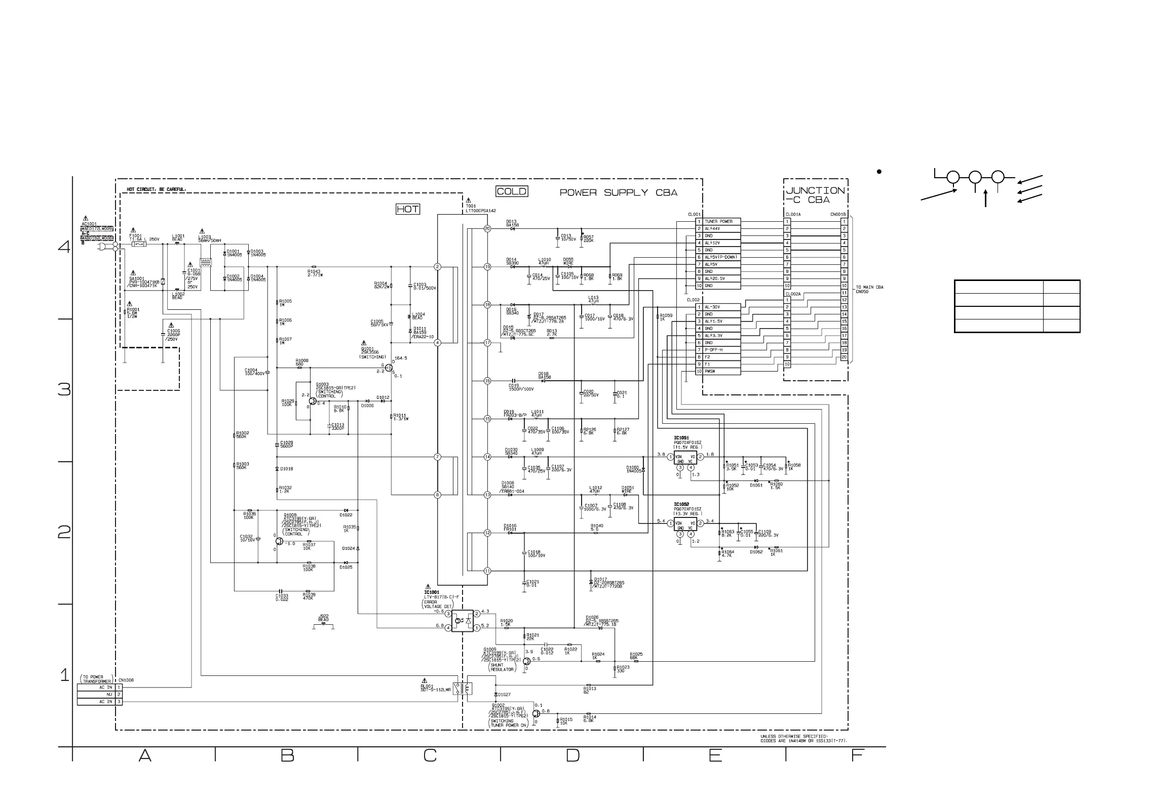
Power Supply (For VCR/DVD) & Junction-C Schematic Diagram < VCR Section >
1-12-37
1-12-38
E9015SCP
“ “ = SMD
THE SAME VOLTAGE FOR BOTH
PLAY, REC & DVD MODES.
INDICATES THAT THE VOLTAGE
IS NOT CONSISTENT HERE.
PLAY MODE
REC MODE
1
2
3
5.0
5.0
(2.5)
<5.0>
~
DVD MODE
Comparison Chart of
Models and Marks
MODEL MARK
MX5100VR/00 A
MX5100VR/05 B
MX5100VR/02 C
BECAUSE A HOT CHASSIS GROUND IS PRESENT IN THE POWER
SUPPLY CIRCUIT , AN ISOLATION TRANSFORMER MUST BE USED.
ALSO , IN ORDER TO HAVE THE ABILITY TO INCREASE THE INPUT
SLOWLY , WHEN TROUBLESHOOTING THIS TYPE POWER SUPPLY
CIRCUIT , A VARIABLE ISOLATION TRANSFORMER IS REQUIRED.
CAUTION !
Fixed voltage ( or Auto voltage selectable ) power supply circuit is used in this unit.
If Main Fuse (F1001) is blown, check to see that all components in the power supply
circuit are not defective before you connect the AC plug to the AC power supply.
Otherwise it may cause some components in the power supply circuit to fail.
NOTE :
The voltage for parts in hot circuit is measured
using hot GND as a common terminal.
CAUTION !
For continued protection against fire hazard,
replace only with the same type fuse.
www.freeservicemanuals.info