4.1.2
RF
sweep part
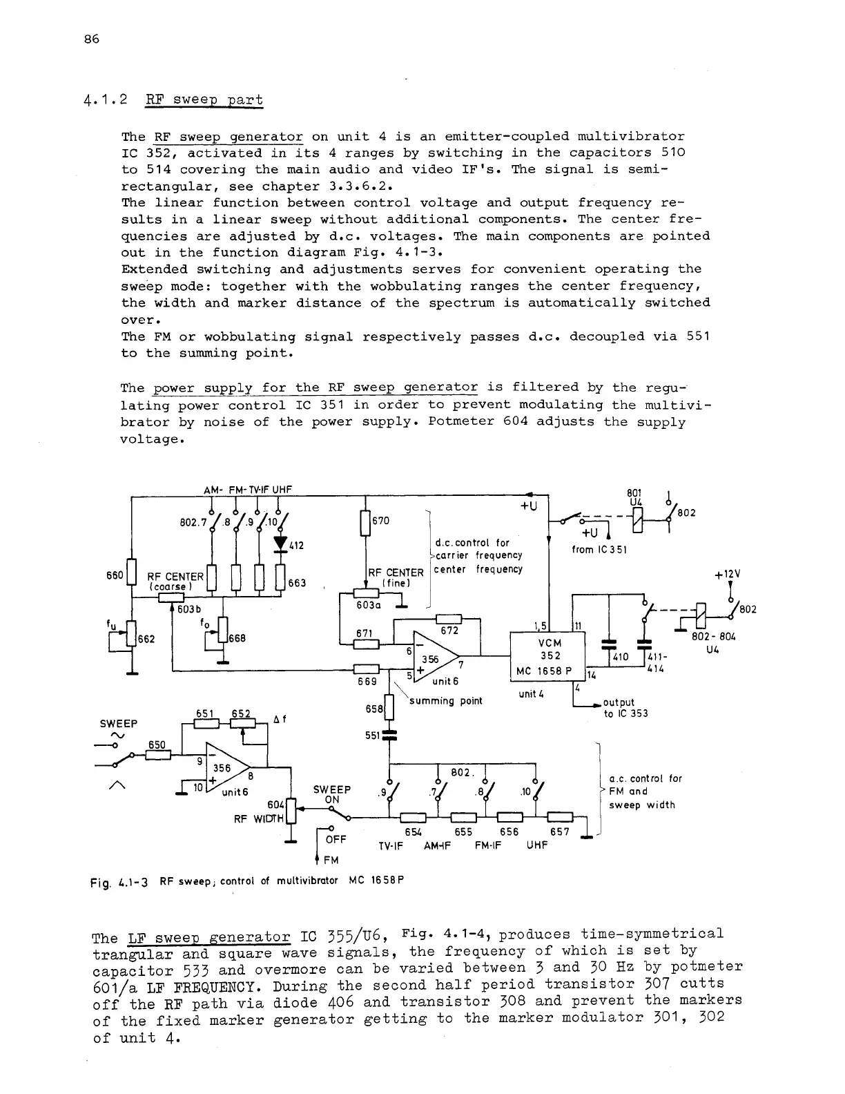
The
RF
sweep generator on unit 4
is
an emitter-coupled multivibrator
IC
352, activated in
its
4 ranges by switching in the capacitors 510
to
514
covering the main audio and video IF
's.
The signal
is
semi-
rectangular, see chapter 3.3.6.2.
The linear function between control voltage and output frequency
re-
sults in a linear sweep without additional components. The center £re-
quencies are adjusted by d.~. voltages. The main components are pointed
out in the function diagram Fig. 4.1-3.
Extended switching and adjustments serves for convenient operating the
sweep mode: together with the wobbulating ranges the center frequency,
the width and marker distance of the spectrum
is
automatically switched
over.
The FM or wobbulating signal respectively passes d.c. decoupled via 551
to the summing point.
The power supply
.-
for the
RF
sweep generator
is
filtered by the regu-
lating power control
IC
351 in order to prevent modulating the multivi-
brator by noise of the power supply. Potmeter 604 adjusts the supply
voltage.
1
FM
Fig.
L.l-3
RF
sweep;
control
of
multivibrator
MC
1658P
The
LF
sweep generator
IC
355/u6,
Fig* 4-1-4,
produces time-symmetrical
trangular and square wave signals, the frequency of which is set by
capacitor
533
and overmore can be varied between
3
and
30
Hz
by potmeter
601/a
LF FREQUENCY.
During the second half period transistor
307
cutts
off the
RF
path via diode 406 and transistor 308 and prevent the markers
of the fixed marker generator getting to
the marker modulator
301,
302
of
unit
4.