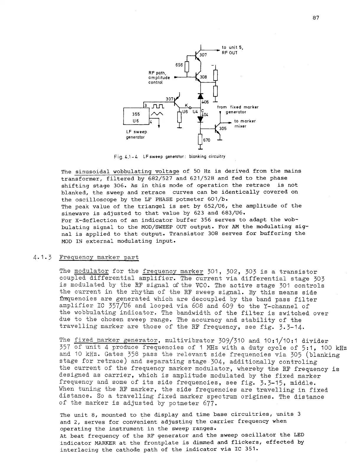
to
unit
5,
RF
OUT
,
7
generator
LF
sweep
1.
%'--
generator
(1670
Fi
9.
L.1
-
L
LF
sweep generator
:
blanking circuitry
The sinusoidal wobbulating voltage of 50 Hz
is
derived from the mains
transformer, filtered by 682/527 and 621/528 and fed to the phase
shifting stage 306.
As
in this mode of operation the retrace
is
not
blanked, the sweep and retrace curves can be identically covered on
the oscilloscope by the LF PHASE
potmeter 601/b.
The peak value of the triangel
is
set by 652/U6, the amplitude of the
sinewave
is
adjusted to that value by 623 and 683/U6.
For X-deflection of an indicator buffer 356 serves to adapt the wob-
bulating signal
to the
MOD/SWEEP OUT output.
For
AM
the modulating sig-
nal
is
applied to that output. Transistor 308 serves for buffering the
MOD
IN
external modulating input.
4.1.3
Frequency marker part
The modulator for the frequency marker
301, 302, 303
is a transistor
coupled differential amplifier. The current via differential stage
303
is modulated by the
RF
signal ofthe
VCO.
The active stage
301
controls
the current in the rhythm of the RF sweep signal. By this means side
muencies
are generated which are decoupled by the band pass filter
amplifier
IC
357/~6
and looped via
608
and
609
to the Y-channel of
the wobbulating indicator. The bandwidth of the filter is switched over
due to the chosen sweep range. The accuracy and stability of the
travelling marker are those of the RF frequency, see fig.
3.3-14.
The fixed marker generator, multivibrator
309/310
and
10:1/10:1
divider
357
of unit
4
produce frequencies of
1
MHz
with a duty cycle of
5:1,
100
kHz
and
10
kHz. Gates
358
pass the relevant side frequencies via
305
(blanking
stage for retrace) and separating stage
304,
additionally controling
the
current of the frequency marker modulator, whereby the
RF
frequency is
designed as carrier, which is amplitude modulated by the fixed marker
frequency and some of its side frequencies, see fig.
3.3-15,
middle.
When tuning the RF marker, the side frequencies are travelling in fixed
distance. So a travelling fixed marker spectrum origines. The distance
of the marker is adjusted by potmeter
677.
The unit 8, mounted to the display and time base circuitries, units
3
and
2,
serves for convenient adjusting the carrier frequency when
operating the instrument in the sweep ranges.
At
beat frequency of the RF generator and the sweep oscillator the LED
indicator MARKER at the frontplate
is
dimmed and flickers, effected by
interlacing the cathode path of the indicator via
IC
351.