EasyManua.ls Logo

Philips VR540/39 User Manual

Philips VR540/39
57 pages
To Next Page IconTo Next Page
Page #1 background imageLoading...
Page #1 background image
Service Manual
Service
Service
Service
Video Cassette Recorder
Contents
Chapter
Schematic Diagrams and CBA's
Exploded Views
Mechanical and Electrical Parts Lists
Sec. 1:
Survey of versions:
/02 PAL B/G
/07 PAL I, Ireland
/16 PAL B/G, Spain
/39 SECAM L,L' & PAL B/G
/58 PAL/SECAM B/G, D/K
Safety regulations require that the set be restored to its original
condition and that parts which are identical with those specified
be used.
Published by BK 2003 Video Service Department Printed in Japan c
Copyright reserved Subject to modification GB 3103 785 22170
For technical data reference is made to the Service Manual of VR540/02/07/16
3103 785 22160. The present manual states only the differences.
VR540/39
VR540/58
VR740/02
VR740/07
VR740/16
VR740/58
VR742/16
VR742/39
VR742/58
Question and Answer IconNeed help?

Do you have a question about the Philips VR540/39 and is the answer not in the manual?

Philips VR540/39 Specifications

General IconGeneral
TypeVCR
Number of Heads4
Remote ControlYes
Playback FormatsVHS
Recording FormatsVHS
Recording SpeedSP
Playback SpeedSP, LP
InputsRF, Composite
OutputsRF, Composite, SCART
ConnectionsSCART
TunerAnalog

Summary

Operating Controls and Functions

Remote Control Operation

Details the functions and buttons of the VCR remote control for comprehensive operation.

VCR and TV Feature Buttons

Explains buttons that control VCR-specific functions and those shared with TV operations.

Device Physical Layout

Front and Back Panel Views

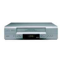
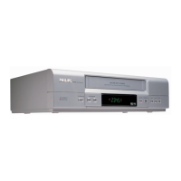
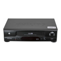
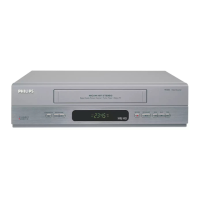
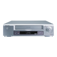
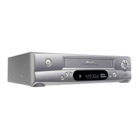
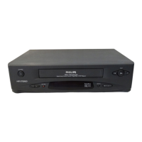
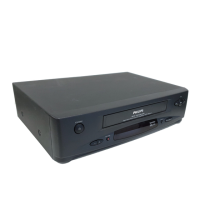
Illustrates the VCR's front panel controls and rear panel connectivity ports.

Signal Name Abbreviations

Cabinet Disassembly Instructions

Disassembly Flowchart and Method

Outlines the step-by-step process for disassembling the VCR cabinet and reassembly notes.

System Block Diagrams

Servo/System Control Block Diagram

Illustrates the main functional blocks and interconnections of the servo and system control circuits.

Video Block Diagram

Audio Block Diagram

Power Supply Block Diagram

Main Schematic Diagrams

Main 1/8 Schematic Diagram

Provides detailed schematic for the main circuit board, section 1/8, covering system control and timers.

Wiring Diagram

IC Pin Function Descriptions

Electrical Parts List

Capacitors List

Lists capacitor part numbers, descriptions, and their presence across different VCR models.

Exploded Views

Front Panel Exploded View

Provides an exploded view illustration of the VCR's front panel components for identification.

Cabinet Exploded Views

Packing Instructions

Related product manuals