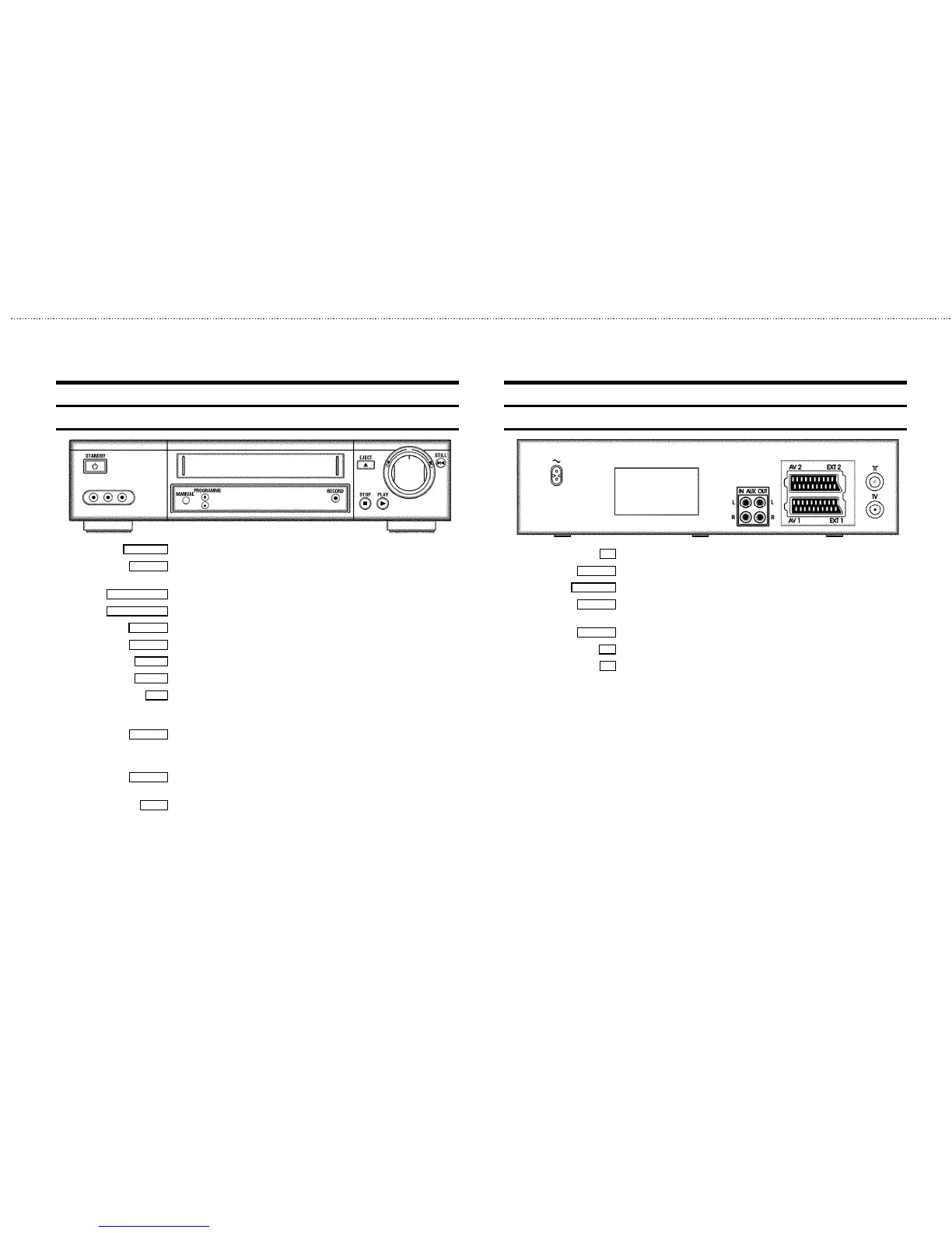
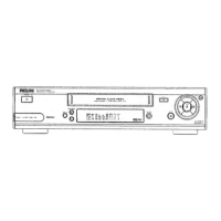
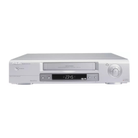
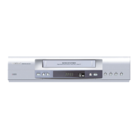
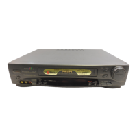
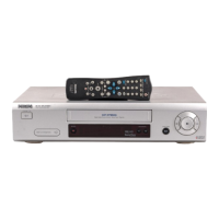
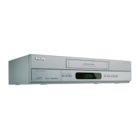
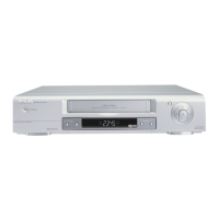
Front of the set
STANDBY m Standby : To switch off, interrupt function, interrupt TIMER recording
MANUAL
Manual sound control : To switch between automatic sound control and manual sound
control
PROGRAMME ;
Programme number Plus: Programme number up
PROGRAMME =
Programme number Minus: Programme number down
RECORD n
Record: To record the programme selected at this moment
EJECT J
Eject: To eject the cassette
STOP h
Pause/Stop: To stop the tape, except during TIMER-recording
PLAY G
Playback : To play back a recorded cassette
o
Rotary control: turn left: during STOP and STANDBY: rewind, during PLAYBACK: reverse
scanning
turn right: during STOP and STANDBY: wind, during PLAYBACK: forward scanning
STILL R
Still picture: To stop the tape and display the actual position on the tape as a still picture
Behind the flap at the lefthand corner on the front:
L AUDIO R
Audio input socket left/right : To connect a camera recorder or video recorder
(programme number ’
E3’)
VIDEO
Video input socket : To connect a camera recorder or video recorder (’E3’)
Back of the set
4 Mains socket: To connect the mains cable
AUX IN L R
Audio input socket, left/right : To connect a HiFi-set (programme number ’AUX’)
AUX OUT L R
Audio output socket, left/right : To connect a HiFi-set
EXT.2 AV 2
Scart socket 2: To connect a satellite receiver, decoder, video recorder, etc. (programme
number ’
E2’)
EXT.1 AV 1
Scart socket 1: To connect the TV set (programme number ’E1’)
2
Aerial input socket: To connect the aerial cable
3
Aerial output socket: To connect the TV set