14
5. UsageOperation and
When the unit fails, the fault code displays in the main display area, press the up or down
button, faults will display in cycle. Press the On button to return to the main interface.
5.2.5 fault interface
Press the up or
down button to
check faults
Press the
On/Off key to
return the main
interface
You could determine or remove failures according to the following malfunction table:
5.2.6 Malfunction table
Malfunction
Reason
Code
Solution
High pressure protection
3 times and above
P1
P2
P3
P4
P5
P6
P7
P8
E0
E8
High pressure protection
Exhaust overtemperature
Protection
Air return temperature
sensing fault
Coil temperature sensing
fault
Exhaust temperature
sensing fault
Humidity sensing fault
Fan feedback signal fault
Communication fault
Exhaust overtemperature
protection 3 times and above
High pressure switch off
3 times and above
High pressure switch off
Compressor overload
Compressor overload 3
times and above
Air return temp. Sensing
head open or short circuit
Coil temperature sensing
head open or short circuit
Exhaust temperature sensing
head open or short circuit
Humidity sensing open or
short circuit
Fan feedback signal open or
short circuit
Remote controller and main
board communication error
Check the pressure switch and the
cooling circuit
Check the pressure switch and the
cooling circuit
Check that the system compressor
operation
Check and replace the return air
temperature head
Check and replace coil temperature head
Check and replace the exhaust
temperature head
Check and replace the humidity sensor
Check the fan feedback signal
Check remote controller and main
board/wiring
Check that the system compressor
operation
P9
P0
Check and replace the ambient
sensor
Ambient temp .Sens or
failure
Ambient sensor open or
short circuit
Ambient overtemperature
or too cold protection
Ambient temperature
overheat or too cold
15
TEMP1
COM
NO
COMP
N1
N2
TEMP2
EEV
COMM_3
HPS
RH_1 RH_2
OP_LED
FM_DC
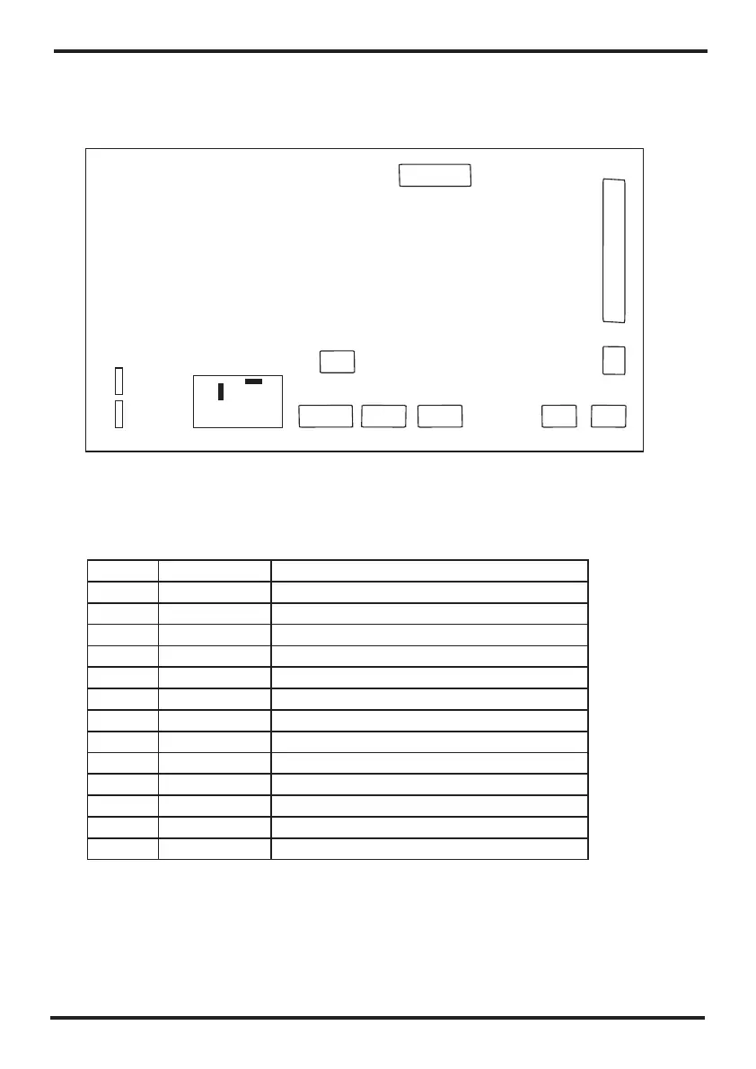
5.3. Controller interface diagram and definition
The input and output interfaces of the mainboard are described below.
N1
Number
Symbol
The definition of the ports
01
02
03
04
05
06
07
08
09
10
11
12
13
Power supply zero line
Compressor zero line
Power line
Compressor output port
Fan output
Wire communication
No use
High pressure protection
Electronic expansion valve
Return air temperature / coil temperature
Exhaust temperature/Ambient temperature
No use
Humidity detection
RH_2
RH_1
TEMP2
TEMP1
EEV
HPS
OP_LED
COMM_3
FM_DC
NO
COM
N2
5. UsageOperation and
CS1000