Connecting or removing cables
7982_en_07 PHOENIX CONTACT 79 / 148
7.10.3 Connecting digital sensors and actuators using the
different connection technologies
1-wire technology
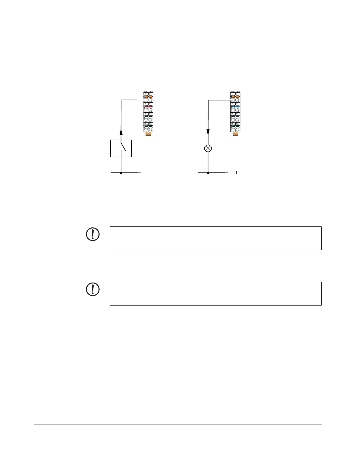
Figure 7-11 1-wire termination for digital modules
Sensor Figure 7-11, A, shows the connection of a 1-wire sensor.
– The SW switch provides the input signal.
– The sensor signal is routed to terminal point IN1.
– The sensor is supplied with a 24 V voltage.
Actuator Figure 7-11, B, shows the connection of a 1-wire actuator.
– The actuator is supplied by output OUT1.
– The load is switched directly via the output.
NOTE: Malfunction
To ensure the correct function, supply the sensors and U
I
from a power supply with a
common GND as the reference potential.
NOTE: Malfunction
To ensure the correct function, make sure that GND of the actuators and GND of the
supply voltage U
o
, which supplies the actuators, have the same potential.
 Loading...