Grounding and shielding
7982_en_07 PHOENIX CONTACT 91 / 148
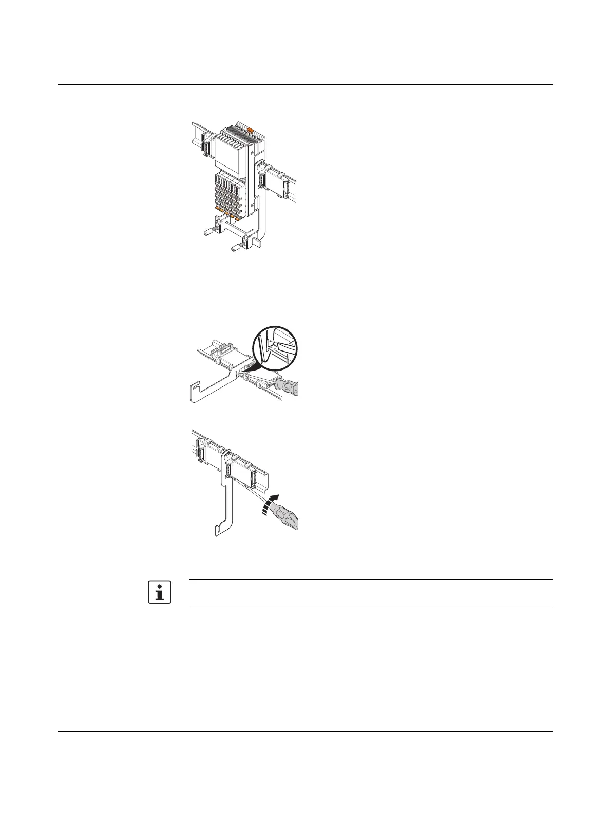
Figure 8-7 Mounting the electronic modules
Removal For removal, use a screwdriver with a blade width of 4 mm (see accessories for examples).
Figure 8-8 Removing the shield connection
• Mount the electronics modules.
• First, remove the adjacent electronics
modules (to the right and left of each
busbar holder).
• Insert the screwdriver in the release
slot.
• Turn the screwdriver to release the
locking clip from the DIN rail.
• Remove the busbar holder.
The locking clip may become deformed following contact with the screwdriver. In this
case, bend it back into shape prior to reassembly.
 Loading...