RAD-...-IFS
26 / 198
PHOENIX CONTACT 105542_en_05
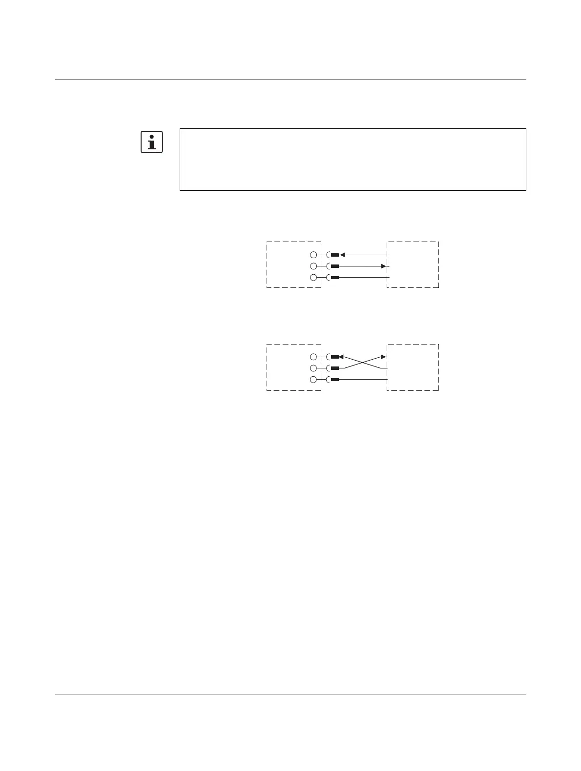
3.6.4 RS-232 pin assignment
In RS-232 mode, point-to-point connections can be established.
According to the standard, you can connect a type DCE device (Data Communication
Equipment) to the RS-232 interface using a 1:1 cable (Figure 3-10). It is also possible to
connect a DTE device using a crossed cable (Figure 3-11).
Figure 3-10 RS-232 interface pin assignment (DTE - DCE)
Figure 3-11 RS-232 interface pin assignment (DTE - DTE)
If you are not sure whether the device to be connected is of DTE or DCE type, you can also
measure the voltage. Measure the voltage between Tx and GND in the idle state:
– Voltage of approximately -5 V: DTE device
– Voltage of approximately 0 V: DCE device
– The RS-232 interface of the wireless module is of DTE type (Data Terminal Equip-
ment). This means that terminal point 5.2 (Tx) is always used to transmit and terminal
point 5.1 (Rx) is always used to receive.
– Only connect the wireless module to devices which meet the requirements of
EN 60950.
COMBICON
RX (5.1)
TX (5.2)
GND (5.3)
D-SUB-9
RX (2)
TX (3)
GND (5)
PLC (DCE)
RS-232
COMBICON
RX (5.1)
TX (5.2)
GND (5.3)
D-SUB-9
RX (2)
TX (3)
GND (5)
PC (DTE)
RS-232

 Loading...

