Do you have a question about the Phoenix Gold ZX600ti and is the answer not in the manual?
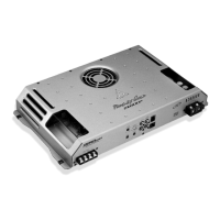
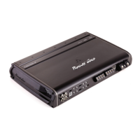
Details advanced cooling systems and high-current output stages for peak performance.
Explains silent turn-on/off muting and LED indicators for thermal/overload protection.
Covers adjustable crossovers, auxiliary outputs, and bass boost functions.
Introduces optional accessories like remote bass control and diagnostic displays.
Provides detailed power output, impedance, and physical dimensions for the ZX600Ti.
Lists power output, impedance, and physical dimensions for the ZX400Ti.
Details general performance metrics like THD, SNR, frequency response, and input/power ranges.
Identifies and explains main input, output, power, ground, and remote terminals on the rear panel.
Details the function and adjustment of crossover frequency, input sensitivity, and bass boost controls.
Explains the role and signal routing options for auxiliary output jacks.
Describes how the CONFIG switch affects speaker and auxiliary output signal types.
Explains the function of power-on and protection indicator LEDs for monitoring amplifier status.
Details the LPL Control Port for connecting remote bass level adjustment accessories.
Illustrates various signal routing combinations for speaker and auxiliary outputs based on CONFIG switch settings.
Visualizes the recommended power delivery system for a single amplifier, including fuse and capacitor placement.
Provides a chart to determine the correct power cable gauge based on wattage and length.
Illustrates the power distribution for multiple amplifiers, including fuse blocks and distribution.
States the recommended capacitance for systems with multiple amplifiers for optimal performance.
Demonstrates a system configuration for full-range speaker output and full-range auxiliary output to another amplifier.
Shows a configuration for component speakers with high-pass and subwoofers with low-pass filters.
Illustrates a system using multiple amplifiers to create a bandpass for mid-bass speakers and low-pass for subwoofers.
Demonstrates a setup routing low-pass signals to subwoofers and high-pass signals to speakers.
Shows a configuration for low-pass subwoofers and full-range auxiliary output to another amplifier.
Details a system setup with multiple amplifiers powering low-pass subwoofers, using aux outputs for signal distribution.
Advises on safe mounting locations, emphasizing protection from moisture and debris, and ensuring ventilation.
Outlines specific ventilation requirements for mounting the amplifier within an enclosed rack system.
Guides on connecting speakers in stereo configuration using appropriate terminals and cable gauges.
Explains how to connect speakers for bridged operation, specifying cable size and terminals.
Details the correct preparation and connection of power, ground, and remote turn-on wires to the amplifier.
Instructs on setting input sensitivity and bass controls to minimum before system setup.
Outlines the process for adjusting input sensitivity, crossovers, and levels for optimal system balance.
Provides guidance on using the LPL44 for subwoofer volume adjustment and blending with the system.
Addresses potential causes and solutions for lack of power or output when LEDs are off.
Covers troubleshooting steps for no output when power LEDs are lit, related to signal or cables.
Explains how to identify and resolve distorted audio output due to clipping or high sensitivity.
Discusses causes and solutions for the amplifier shutting down due to overheating (yellow LED).
Identifies causes for amplifier shutdown due to excessive output current (red LED).
Guides on inspecting speaker cables, voice coils, and passive crossovers for damage.
Mentions scenarios like defective output transistors requiring service center repair.
Lists contact details for Phoenix Gold authorized service centers for repairs.
Outlines the terms, conditions, and time periods covered by the limited warranty.
Lists specific circumstances and actions that will void the product warranty.
Details the consumer's sole remedies and the manufacturer's liability limitations under the warranty.
| RMS Power at 4 Ohms | 150W x 2 |
|---|---|
| RMS Power at 2 Ohms | 300W x 2 |
| Bridged RMS Power at 4 Ohms | 600W x 1 |
| Frequency Response | 10 Hz - 30 kHz |
| Signal-to-Noise Ratio | > 100 dB |
| THD | <0.05% |
| Input Sensitivity | 200 mV - 6 V |