6
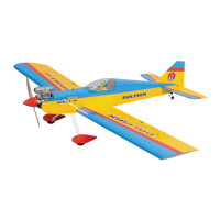
DOLPHIN
Instruction Manual
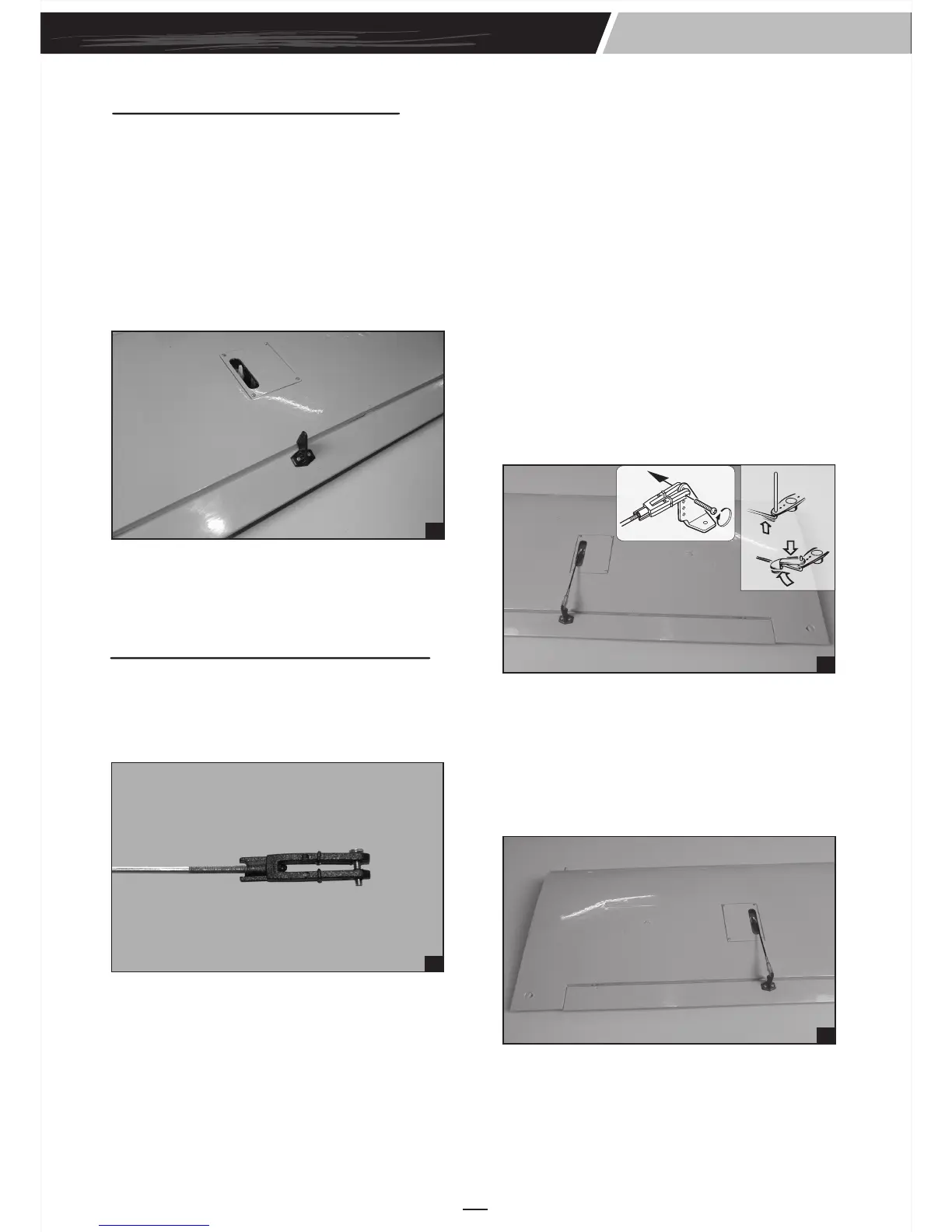
INSTALLING THE CONTROL HORNS
1. One aileron control horn in positioned on each
aileron. Using a ruler and a pen, locate and
mark the location of the control horn. It should
be mounted on the bottom side of the aileron at
the leading edge, in line with the aileron
pushrod.
7
2. Drill two 1.6mm holes through the aileron using
the control horn as a guide and screw the
control horn in place.
9. Repeat step # 4 - # 8 to install the second
aileron linkage. After both linkages are
completed, connect both of the aileron servo
leads using a Y-harness you have purchased
separately.
10
9
3. Repeat step # 1 - # 2 to install the control horn
on the opposite aileron.
6. With the aileron and aileron servo centered,
carefully place a mark on the aileron pushrod
wire where it crosses the hole in the servo arm.
7. Using pliers, carefully make a 90 degree bend
down at the mark made. Cut off the excess
wire, leaving about 4mm beyond the bend.
8. Insert the 90 degree bend down through the
hole in the servo arm. Install one nylon snap
keeper over the wire to secure it to the arm.
Install the servo arm retaining screw and
remove the masking tape from the aileron.
4. Plug the aileron servo into the receiver and
center the servo. Install the servo arm onto the
servo. The servo arm should be perpendicular
to the servo and point toward the middle of the
wing.
5. Center the aileron and hold it in place using a
couple of pieces of masking tape.
2. Attach the clevis to the outer hole in the control
horn.
3. Locate one nylon servo arm, and using wire
cutters, remove all but one of the arms. Using a
2mm drill bit, enlarge the third hole out from the
center of the arm to accommodate the aileron
pushrod wire.
INSTALLING THE AILERON LINKAGES
1. Working with the aileron linkage for now, thread
one nylon clevis at least 14 turns onto one of
the 2mm x 180mm threaded wires.
8