©2014 Phoenix Controls Specifications subject to change without notice. Rev. C 650-321-017 08/16 PCS300 SERIES INSTALLATION GUIDE 5 OF 12
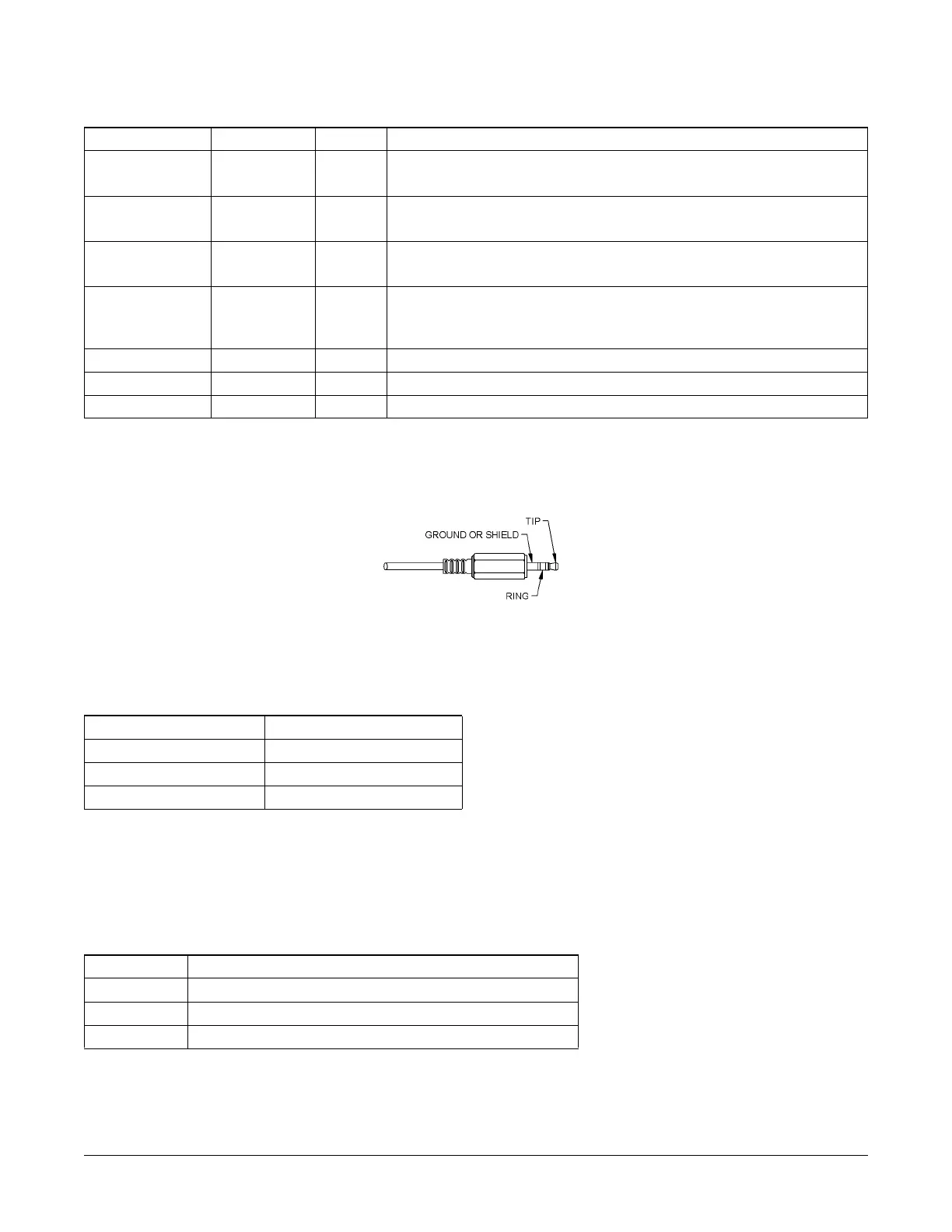
2.2.3 Communication Jack Wiring
Figure 4. Communication jack pinout
2.2.4 Test and Balance (T&B)
Moving the Test and Balance (T&B) switch to the Normal position provides the actual room temperature. Moving the switch to HI forces a high
temperature value for the balancer or point-to-point checkout. Moving the switch to LO forces a low temperature value.
PHS300-x, PCS300-x, and PCS300-x-DOS Wiring with Jumper in: 0-5 Vdc or 0-10 Vdc Settings
Terminal Applicable to: Option Description
OVR1 and OVR2 PCS300-x-DOS
only
O Occupancy override status:
N.O. contact output (300 mA @ 30 Vdc)
SET1 and SET2 PCS300-x-DOS
only
S Temperature setpoint:
0 -20 KΩ output
SEN1 and SEN2 PCS300-x and
PCS300-x-DOS
Temperature sensor:
10K-2 thermistor output
EXT-OVR PCS300-x-DOS
only
D External "person" icon override:
Bypass control (from Phoenix valve) indication; "person" icon is solid (occupied) when
this pin is switched to power ground (see Bypass/External "Person" Icon Control on page 7)
VOUT All Humidity sensor: 0-5 Vdc or 0-10 Vdc output
GND All Power ground
V+ All 24 Vdc power (see Specifications on page 10 for details)
Communication Female Jack Wiring
Communication Jack Pin Wire Color
Ground Black (Net B)
Tip White (Net A)
Ring Red (Not used)
Test and Balance Switch Settings
Switch Position Description
HI Sets the sensor value HIGH for full cooling (5.11Ω, 105.8°F)
NORMAL Allows sensor to operate normally; reports actual temperature
LOW Sets sensor value low for full heating (26.7KΩ, 39.2°F)