3
www.UsePhoenix.com • sales@UsePhoenix.comToll-Free 1-800-533-7533
3.2 Electrical Requirements
The Phoenix R175 plugs into a common grounded outlet on
a 15 amp circuit. It draws 6.3 amps at 80°F, 60% RH. If used
in a wet area, a ground fault interrupter (GFI) is required. If
an extension cord is required, it must have a minimum of
14 gauge conductors if 25 feet long or less and 12 gauge
conductors if greater than 25 feet long.
3.3 Condensate Removal
The Phoenix R175 is equipped with an internal condensate
pump to remove the water that is condensed during
dehumidication. This allows the condensate to be pumped
20 feet with the attached hose. If the condensate must be
pumped more than 20 feet above the unit, a second pump
must be added to relay the condensate. The condensate
pump automatically purges for 20 seconds every eight
minutes. Use the PURGE button to manually remove
condensation.
3.4 Ducting
A wire duct collar is supplied to allow 10” lay-at duct to be
attached to the Phoenix R175 outlet. Lay-at plastic ducting
is available; see accessories table page 6. To attach ducting
to the wire duct collar, put the plastic duct end through the
collar center and roll the duct end outward so that it overlaps
the outside of the collar. The duct and collar may then be
quickly attached to the Phoenix R175 by snapping the collar
over the four exhaust tabs.
3.5 Defrost Cycle
If the low side refrigerant temperature drops due to excessive
frost formation on the evaporator coil and below the tempera-
ture set point, the thermistor activates the solid-state control
and defrost light. The compressor is cycled off and on by the
thermistor temperature measurement. The air mover will
continue to run, causing air to ow through the evaporator
coil and melt the ice when the compressor is off. When the
air temperature and/or humidity increases, the evaporator
temperature will rise and the thermistor will end the defrost
cycle at the temperature set point.
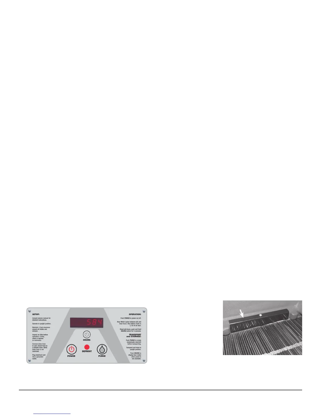
3.6 POWER Button
Press the POWER button to turn the dehumidier on or off.
When starting the dehumidier the display will show the
accumulated hours. Press the POWER button again to turn
the dehumidier off. The display will also power off.
3.7 PURGE Button
During normal operation the pump automatically cycles every
four minutes. Press the PURGE button to remove condensate
manually from the reservoir. There are several ways to
manually remove water from the reservoir:
1. Press the PURGE button once and the pump will run for
20 seconds
2. Press and hold the PURGE button and the pump will run
for up to 30 seconds
3. Press the PURGE button while the dehumidier is
powered off and the pump will run for 30 seconds.
Always manually purge the water reservoir before transport
or storage. Turn off the power and allow the plugged in
dehumidier to rest 15 minutes before the nal purge.
3.8 Hour Meter
The digital hour meter displays the amount of time the
dehumidier has been turned on to the tenth of an hour. The
hour meter continuously cycles between total machine hours
and job hours every 3 seconds. Hours are stored in memory
even when the unit is unplugged. The previous totals will be
displayed next time the unit is powered on.
3.9 HOURS Button
Pressing the HOURS button displays the hour meter when the
unit is turned off but plugged into power. To reset job hours,
press and hold the HOURS button for 5 seconds when the
unit is operating.
3.10 DEFROST Light
The DEFROST light turns on when the unit is in defrost cycle
and indicates when the compressor is off.
3.11
Bypass Control
Below 90°F - When
operating the Phoenix
R175 below 90°F, the
bypass cover must close
the bypass holes, gure
3. This maximizes the
amount of air that is
dehumidied across the
evaporator. These cooler
temperatures are often found during the rst 24 hours of a
drying job.
Figure 2: Phoenix R175 control board.
Figure 3
Bypass Cover