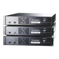
7MAX 1000 / 1600
OPERATION
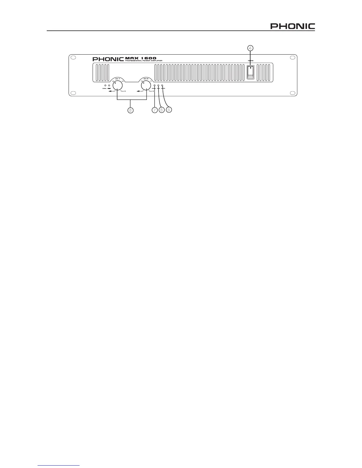
FRONT PANEL
4. POWER SWITCH
This switch turns the power of the unit on. Remember to
turn the gain controls down before turning power on or off,
even though it comes with a POWER ON / OFF MUTING
feature. In general, the power amplier should be the last
piece of audio equipment to be powered on, and the rst
to be powered off, in a PA system.
5. POWER LED
This blue LED comes on when power is on.
6. PEAK LED
When the input signal level becomes too high, causing
input signal to loss denition and to distort, this red LED
comes on. When this happens, turn the gain control down
until the PEAK LED no longer comes on or remains on
continuously.
7. SIGNAL LED
Every channel comes with a signal LED, allowing user to
monitor signal level. A minimum level of -30dBu is required
for the LED to go on.
8. GAIN CONTROLS
These two rotary knobs control the signal level of the input.
Center detented control allows precise volume setting.
Slowly turn the knob clockwise to increase input level, but
make sure that PEAK LED does not remain on or blink
constantly.
REAR PANEL
9. PARALLEL / STEREO / BRIDGE MONO
OPERATION MODE
There are three operation modes for different use. To
avoid damaging your PA system, remember to turn the
power off before switching from one mode to the other.
See the OPERATING MODES section of this manual for
more details.
10. GROUNDING/FLOATING SWITCH
This switch allows the circuit and chassis grounds to be
separated in case of a ground conict. In normal use the
switch should be in the Ground On position. Lifting the
ground (Floating position) may resolve the ground conict,
but means that circuit grounding will depend on other con-
nected components. Deciencies in other components’
grounding will affect the sound and a serious electric fault
with the amplier could damage other components in the
system.
11. CHASSIS GROUNDING CONNECTING POINT
To avoid the possibility of ground loop, this unit comes with
chassis grounding point allowing it to be connected to other
units for sharing a common grounding.
12. POWER CORD
This cord draws electricity from power outlet. Near by you
will nd an indicator that tells you what voltage your unit
operates in. Check the AC voltage of your unit before con-
necting the power plug to the outlet and ensure that the AC
requirements of your MAX amplier are the same as those
used in your country.
13. RESET SWITCH
Push this button to reset the unit in the unlikely event that
it locks up.
 Loading...