Do you have a question about the Phonic MAX 500 and is the answer not in the manual?
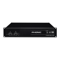
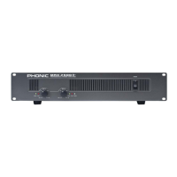
Controls the input signal level for each channel.
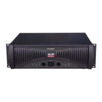
Indicates protection circuit activation for the MAX500.
Shows when the amplifier's output signal is clipping.
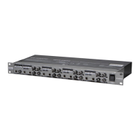
Connectors for audio sources, accepting XLR and 1/4" phone jacks.
Selects operation mode: stereo or parallel signal routing.
Separates circuit and chassis grounds to resolve conflicts.
Explains using the amplifier for bi-amplification setups.
Illustrates the internal functional circuitry of the amplifier.
| Channels | 2 |
|---|---|
| Connectors (Inputs) | XLR and 1/4" TRS |
| Input Impedance | 20kΩ balanced, 10kΩ unbalanced |
| Protection | Thermal, short circuit |
| Connectors (Outputs) | Binding Post and Speakon |
| Cooling | Fan Cooled |