Do you have a question about the Phonic ICON 700 and is the answer not in the manual?
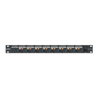
Controls the power ON/OFF state of the amplifier, indicated by an LED.
Indicates protection activation due to turn-on, faults, thermal issues, or short circuits.
Lights up at clipping status, signaling potential waveform distortion or load problems.
Indicates the presence of an audio signal at the channel input, typically at -26dB.
Lights up when the limiter reduces input signal level to prevent clipping (Icon 700 only).
Adjusts the input signal level for each channel; turn clockwise to increase gain.
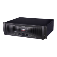
Balanced input connectors for mixers and preamps.
Provides secure connections for permanent installations.
XLR output connectors for parallel connection to other amplifiers.
Selects operating mode: Stereo, Parallel, or Bridge Mono.
Barrier strips for connecting low impedance speakers.
Barrier strips for connecting distributed line (25V, 70V, 100V, etc.) speakers.
Connect signal to CH1 input only; use CH1 gain control for level setting.
For 140V/200V lines, use CH1 input only; set level with CH1 gain control.
| Number of Channels | 2 |
|---|---|
| Amplifier Type | Power Amplifier |
| Output Power | 700W RMS per channel at 8 Ohms |
| Frequency Response | 20 Hz to 20 kHz, +0/-1 dB |
| Input Impedance | 20k Ohms balanced, 10k Ohms unbalanced |
| Cooling | Fan-cooled |
| Protection | Short circuit, DC, overload |
| Connectors (Input) | XLR, 1/4" TRS |
| Connectors (Output) | Binding Posts, Speakon |
| Dimensions | 482 x 88 x 395 mm (19 x 3.5 x 15.6") |