Installation
Manual piCOMPACT
®
23 SMART IO-Link Ready 2 channel Page 9/24
4. Installation
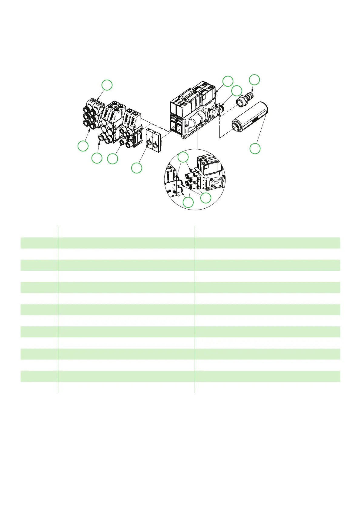
4.1 Connections, 2 channels
2a
1
2d
2b
6
7
8
1
4
2c
5
2a
3c
2d
2b
3d
Figure 2 Connections, 2 channels.
Pos. Description Size
1 Compressed air (common feed) Push-in: Ø6 / Ø1/4’’ / Ø8 (Ø5/16’’) / Ø10 / Ø3/8”
2a Vacuum port (1-3 ports) Push-in: Ø10 / Ø3/8’’ / Ø12 / Ø1/2’’ Barb: Ø12 /Ø1/2’’
2b Vacuum port (1-3 ports) Push-in: Ø10 / Ø3/8’’ / Ø12 / Ø1/2’’ Barb: Ø12 /Ø1/2’’
2c Vacuum port (1-3 ports) Push-in: Ø8 (Ø5/16’’) / Ø10 / Ø3/8’’
2d Vacuum port Push-in: Ø10
3c Central exhaust (no side mounted silencer)
3d Central exhaust, side mounted central silencer
4 Connector (one connector/ channel) M12 5p, A-code
5* Sensor connection split Ø4
6* Valve air connection split (vacuum) Push-in: Ø6 / Ø1/4’’ / Ø8 (Ø5/16’’) / Ø10 / Ø3/8”
7* Blow-off air connection split Push-in: Ø6 / Ø1/4’’ / Ø8 (Ø5/16’’) / Ø10 / Ø3/8”
8 Sensing port Plugged / G1/8”
7* Blow-off air connection split Push-in: Ø6 / Ø1/4’’ / Ø8 (Ø5/16’’) / Ø10 / Ø3/8”
8 Sensing port Plugged / G1/8”