Page 7.7
PROGRAMMABLE POTENTIOMETER MODULE 40-296
pickering
SECTION 7 - MAINTENANCE INFORMATION
CALIBRATION
The 40-296 has no user adjustable components. In most applications regular calibration is not required; however
for applications where a routine calibration is required for a system we suggest the following functional test for the
module.
The 40-296 should be tested with a 6.5 digit DMM or better. The user must use a 4 terminal resistance measurement
to avoid the introduction of errors due to leads.
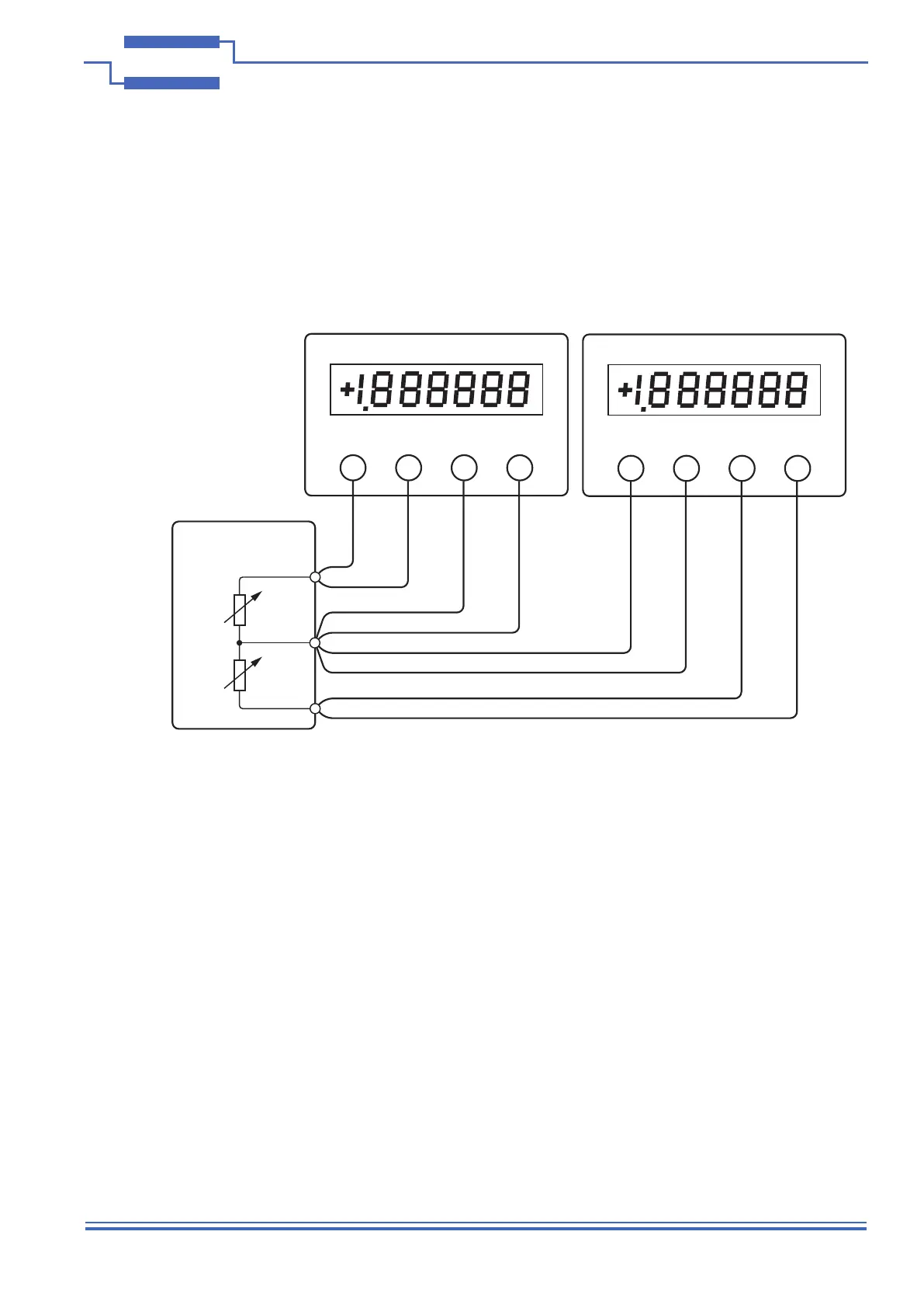
The user should test each side of the potentiometer as a separate resistor channel as shown in Figure 7.3, either
with separate DMMs or by moving the DMM between the two sides. For each channel, connect the 4 wires to the
connector as shown. For automated systems a multiplexer can be used provided the 4 wire measurement system
is maintained.
The procedure is given for the standard modules only; custom modules use the same procedure but must apply
individual limits that reect the accuracy of the resistors tted and the resolution.
To test the module, launch the module soft front panel.
Close all the relays in the selected channel and measure the residual path resistance, note the result (from now
referred to as PATH).
With the channel still set to the minimum resistance use the DMM offset facility to set the reading to ZERO.
For each resistor in the chain close all the relays except for the resistor to be measured
Example: For R1 close all except the relay in parallel with R1, for R2 close all the relays except the relay in
parallel with R2
Record each result for each resistor in the channel. For the tables the results are identied by the resistor number
in each channel
Example: For 8 bit channels each channel will have 9 measurement results consisting of one PATH result and
8 resistors numbered R1 to R8.
Accuracy limits are dependent on the tolerance of the resistor tted and the changes in path resistance. For the
40-296 the measured value is:
(PATH -.05 to -0.2Ω)+ (Nominal resistance ± tolerance)
To eliminate the variability of the PATH result the DMM has been nulled to remove it from the subsequent
measurements. The PATH resistance uncertainty assumes the reed relay path used to switch the resistors has a
minimum contact resistance of 0.05Ω and a maximum of 0.2Ω. A typical value is 0.1Ω.
Table 7.5 show the generic limits for standard modules and Table 7.6 to 7.9 can be used fro recording test results.
6½ Digit DMM
V,Ω+ I+ V,Ω- I-
6½ Digit DMM
V,Ω+ I+ V,Ω- I-
40-296 Programmable
Potentiometer Module
Terminal A
Terminal B
Wiper
Figure 7.3 - Calibration
of the 40-296 using
two DMMs with 4-wire
resistance measurement