SECTION 7 - MAINTENANCE INFORMATION
Page 7.3
pickering
ISOLATED MILLIVOLT THERMOCOUPLE SIMULATOR 41-761
Verication Procedure
The verication procedure describes a set of measurements that are adequate to check that the module is performing
to specication.
The following equipment is required to perform the test
● A DMM with performance at least equivalent to a 6.5 digit model. Example: Keysight 34410A or 34411A
● A cable assembly to connect the DMM to the 41-761. This can be constructed by the user or the user can
purchase a ready made cable from Pickering Interfaces suitable for connecting to the front panel connector.
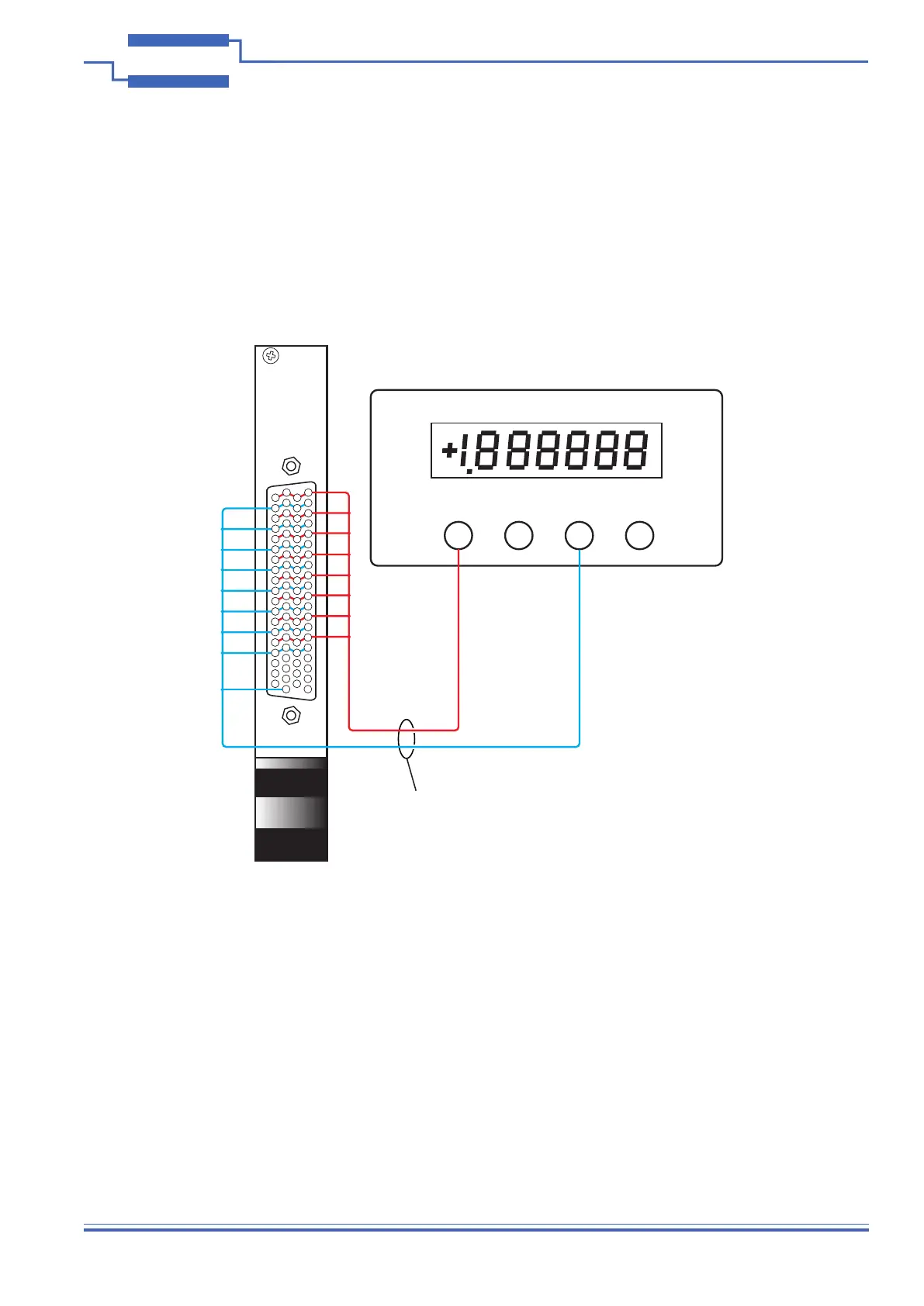
6½ Digit DMM
41-761
V,Ω+ I+ V,Ω- I-
Calibration/Verification Cable
6
7
8
9
1
2
3
4
5
10
11
12
13
21
22
23
24
25
26
27
28
29
30
31
32
14
15
16
17
18
19
33
34
35
36
37
38
20
39
45
46
47
48
40
41
42
43
44
49
50
51
52
60
61
62
63
64
65
66
67
68
69
70
71
53
54
55
56
57
58
72
73
74
75
76
77
78
59
Figure 7.1 - 41-761 Verication Setup Using the Individual Channel Connections
Connecting to the Voltage Channels:
Each channel can be independently veried using the following steps. Results from this verication can be recorded
in the tables in the following pages.
● All channels can be connected in parallel as shown in gure 7.1. This is achieved by connecting all Vo
connections and all Vcold connections, providing a single 2-wire connection to the DMM. The Vcold connection
should also be connected to the module’s Analogue_GND pin, providing a common xed reference point.
● Once a voltage is set on the module, a DMM in a high impedance mode (at least 20MΩ) must be used to
measure the result. The measurement value should be within the range specied in the corresponding table
entry for the set voltage in tables 7.2 to 7.4, observing the associated foot notes.