SECTION 2 - TECHNICAL DESCRIPTION
Page 2.1
pickering
ISOLATED MILLIVOLT THERMOCOUPLE SIMULATOR 41-761
SECTION 2 - TECHNICAL DESCRIPTION
FUNCTIONAL DESCRIPTION
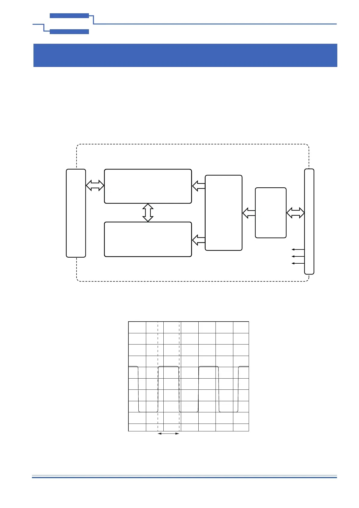
Figure 2.1 - Isolated Millivolt Thermocouple Simulator 41-761: Functional Block Diagram
Logic
Translators
Ux13
PCI
Interface
& Control
Logic
U1 to U6
+5V
Compact PCI Bus Connector J1
PXI ISOLATED MILLIVOLT THERMOCOUPLE SIMULATOR 41-761
Front Panel Connector J2
78-pin Male D-Type
32 Millivolt Generator Channels
Ux14-Ux16, Ux10
+3.3V
GND
Power Convertors
DCx1
A functional block diagram is provided in Figure 2.1. The Isolated Millivolt Thermocouple Simulator Module is
powered by +5V and +3.3V supplies via Compact PCI connector J1. The interface to the user test equipment is via
the front panel mounted 78-pin male D-type connector, J2. The module comprises a PCB populated with 32 millivolt
generator channels designed to function as thermocouple simulators. These are controlled by the PCI interface and
control logic via logic translation devices.
50mV/div
780µs
Figure 2.2 - Voltage Change: 100mV to -100mV High Range 780µs