Page 7.4
SECTION 7 - MAINTENANCE INFORMATION
pickering
ISOLATED MILLIVOLT THERMOCOUPLE SIMULATOR 41-761
VERIFICATION TEST RESULTS
For convenience, Tables 7.2 to 7.4 on the following pages are provided for a means of recording results for one
channel of each model.
Adjustment Procedure
In the unlikely event that adjustment of the 41-761 is required we recommend returning it to Pickering Interfaces.
Adjustment of the 41-761 requires the use of a high performance DMM and an automated program in order to
maintain its accuracy in the event of an adjustment being required to improve performance.
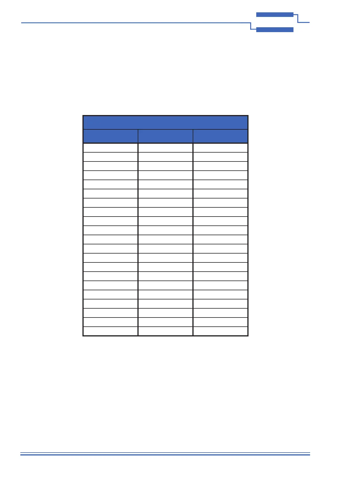
Table 7.1 – Verication Voltage Settings For Each Range
Voltage Range
+/-100mV +/-50mV +/-20mV
-100mV -50mV -20mV
-90mV -45mV -18mV
-80mV -40mV -16mV
-70mV -35mV -14mV
-60mV -30mV -12mV
-50mV -25mV -10mV
-40mV -20mV -8mV
-30mV -15mV -6mV
-20mV -10mV -4mV
-10mV -5mV -2mV
0mV 0mV 0mV
10mV 5mV 2mV
20mV 10mV 4mV
30mV 15mV 6mV
40mV 20mV 8mV
50mV 25mV 10mV
60mV 30mV 12mV
70mV 35mV 14mV
80mV 40mV 16mV
90mV 45mV 18mV
100mV 50mV 20mV
● If the full functionality of the module is to be checked, subsequent voltages and ranges can also be checked in
turn, as dened in table 7.1.
● After a given channel is tested it is recommended that the clear card function is used to ensure each channel
is left in the open state, ensuring it does not affect subsequent channel testing.
● Repeat across all channels as required.