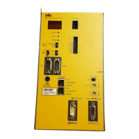
Wiring
5-2 Operating Manual: PSS(1) DI2O Z
Notes on wiring
In addition to the “Notes on wiring” in the “PSS 3000/PSS 3100 Series
Installation Manual”, please note the following:
• Safety-related input signals must operate in accordance with the failsafe
principle (on switching off).
• In the user program, make sure that a “0” signal from the module always
causes the relevant outputs to shut down.
• Do not assign the same test pulse to adjacent inputs.
• Do not connect DIF and DI2 inputs to the same test pulse.
• The max. continuous current over all the outputs must not exceed 10 A.
• When testing the outputs, the load is isolated from the supply for max.
200 µs in each cycle (depending on the load and cable runs). The load
must not drop off during this time.
• Error messages can occur when testing outputs on which the contactors
are smaller than the recommended load. The error messages are
triggered by the high inductance on the contactors. In this case it helps to
have a 1 kOhm resistor connected in parallel to the contactor coil.
• Contactors with a pull-in power of up to 200 W can be driven via
the 2 A outputs.
• Only one 0 V terminal needs to be connected to terminals X1 und X2.
• One of the two 24 V terminals and 0 V terminals must be connected to
terminals X3 and X4.
• Use copper as the conductive material.
• The torque setting on the connection terminals should be 0.5 … 0.6 Nm.
NOTICE
Please refer to the following application examples!
 Loading...