Do you have a question about the Pilz PSS Series and is the answer not in the manual?
Specifies valid software versions for the documentation.
Manual structure and chapter overview.
Explains warning and information symbols used in the manual.
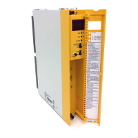
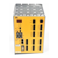
Illustrates front views and components of various PSS models.
Defines proper use, safety regulations, and qualified personnel requirements.
Discusses system classification based on safety standards.
Outlines warranty conditions, liability limitations, and proper disposal.
Details CPU functions and available interfaces (Programming, SafetyBUS p, standard bus).
Describes digital inputs and test pulse outputs functionality and specifications.
Specifies environmental, ventilation, and ESD precautions for installation.
Illustrates physical mounting options for the PSS in a control cabinet.
Details electrical requirements and connection guidelines for the 24 VDC supply.
Shows how to connect external power supplies for systems with and without INTERBUS.
Provides guidelines on cable cross-sections and terminal torque settings.
Explains terminal configurations and connector descriptions for I/O.
Covers earthing, short circuits, open circuits, and cable laying guidelines.
Provides examples for connecting digital inputs, including failsafe devices.
Details the use and connection of dedicated test pulse outputs.
Specifies recommended cabling and grounding for interfaces.
Details RS 232 and RS 485 interfaces for programming the PSS.
Explains RS 232 and RS 485 interfaces for user interaction with the PSS.
Covers SafetyBUS p connections and standard bus interface descriptions.
Guides on system setup, error detection, and troubleshooting procedures.
Explains the meaning of LEDs and display elements for system status.
Provides instructions and precautions for replacing the system battery.
Details supply voltage, current, power, CPU timing, memory, and interfaces.
Covers protection type, operating temperatures, vibration, shock, EMC, weight, and dimensions.
Provides contact details for the SafetyBUS p Club.
Lists revisions and changes made to the documentation.
| Category | Safety Equipment |
|---|---|
| Manufacturer | Pilz |
| Safety Standards | EN ISO 13849-1, IEC 61508, IEC 62061 |
| Series | PSS |
| Safety Integrity Level | SIL 3 |
| Communication Interfaces | Ethernet, PROFIBUS, PROFINET |
| Operating Voltage | 24 V DC |
| Operating Temperature | 0°C to +55°C (typical), others depending on model |
| Storage Temperature | -20°C to +70°C (typical), others depending on model |
| Protection Class | IP20 |
| Application | Industrial safety applications |


 Loading...