Overview
2-6 Operating Manual: PSS SB 3006-3 Series
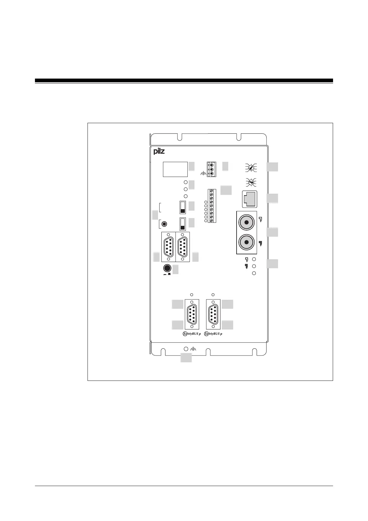
PSS SB2 3006-3 CN-A
Fig. 2-3: Front view of PSS SB2 3006-3 CN-A
Key:
1: 4-digit display
2: LEDs for PSS operating mode and supply voltage
3: 3-position switch for selecting the standard section’s operating mode
4: Button for scrolling the error stack
5: 2-position switch for selecting the failsafe section’s operating mode
RUN FS
RUN ST
POWER
PG
AUTO PG
SPS
ST
FS
STOP
RUN
0 V
T 0
T 1
I 0.0
I 0.1
I 0.2
I 0.3
I 0.4
I 0.5
X1
1
.
.
.
.
.
.
9
PSS SB2 3006-3 CN-A
ON
OFF
R
T
(USER)
1
.
X0
.
3
PSS PWR ADDRESS
x1
6
7
8
9
4
3
2
1
5
0
x10
6
7
8
4
3
2
0
19
5
NAP
B
A
MODULE STATUS
B
A
1
2
3
4
5
10
8
7
F-Stack
PG
6
USER
24 V
0 V
15
16
17
18
19
ControlNet
9
1214
132...195 032...095
0
1
11
STATUS SB
13
STATUS SB
Artisan Technology Group - Quality Instrumentation ... Guaranteed | (888) 88-SOURCE | www.artisantg.com

 Loading...