Interfaces
8-8 Operating Manual: PSS SB 3006-3 Series
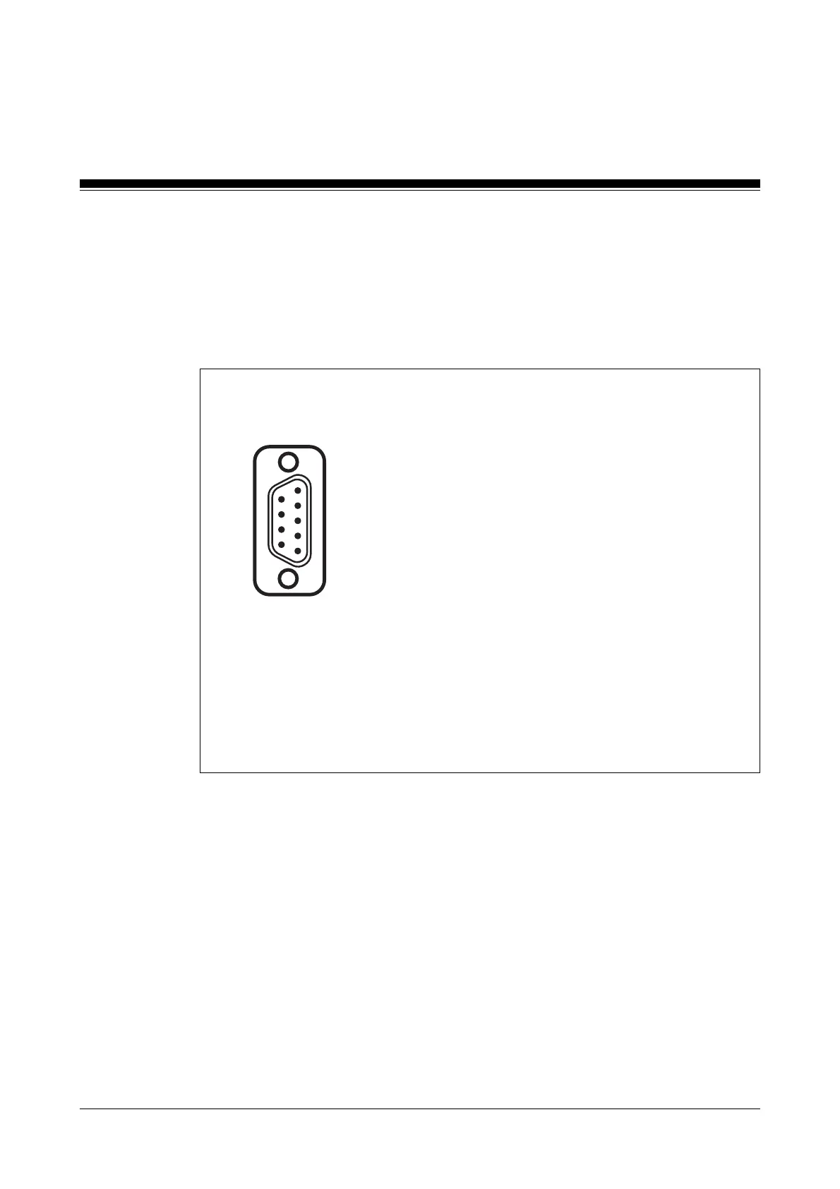
Fig. 8-6: Configuration of the SafetyBUS p interface
1: n.c.
2: CAN_L (brown)
3: CAN_GND (white)
4: n.c.
5: CAN_SHLD
6: n.c.
7: CAN_H (green)
8: Supply voltage for fibre-optic couplers
from Pilz
9: n.c.
n.c. = not connected
Male D-Sub connector
9-pin
SafetyBUS p interface (“SafetyBUS p 0” and “SafetyBUS p 1”)
Connection to SafetyBUS p is via a male 9-pin D-Sub connector. Detailed
information on SafetyBUS p can be found in the SafetyBUS p manual.
5
1
6
9
Interfaces for standard bus connections
The standard bus interfaces are described in separate operating manuals.
The necessary operating manuals are supplied with each programmable
safety system in the PSS SB2 3006-3 series, depending on the unit type.
Artisan Technology Group - Quality Instrumentation ... Guaranteed | (888) 88-SOURCE | www.artisantg.com

 Loading...