Installation
5-2 Operating Manual: PSS SB 3006-3 Series
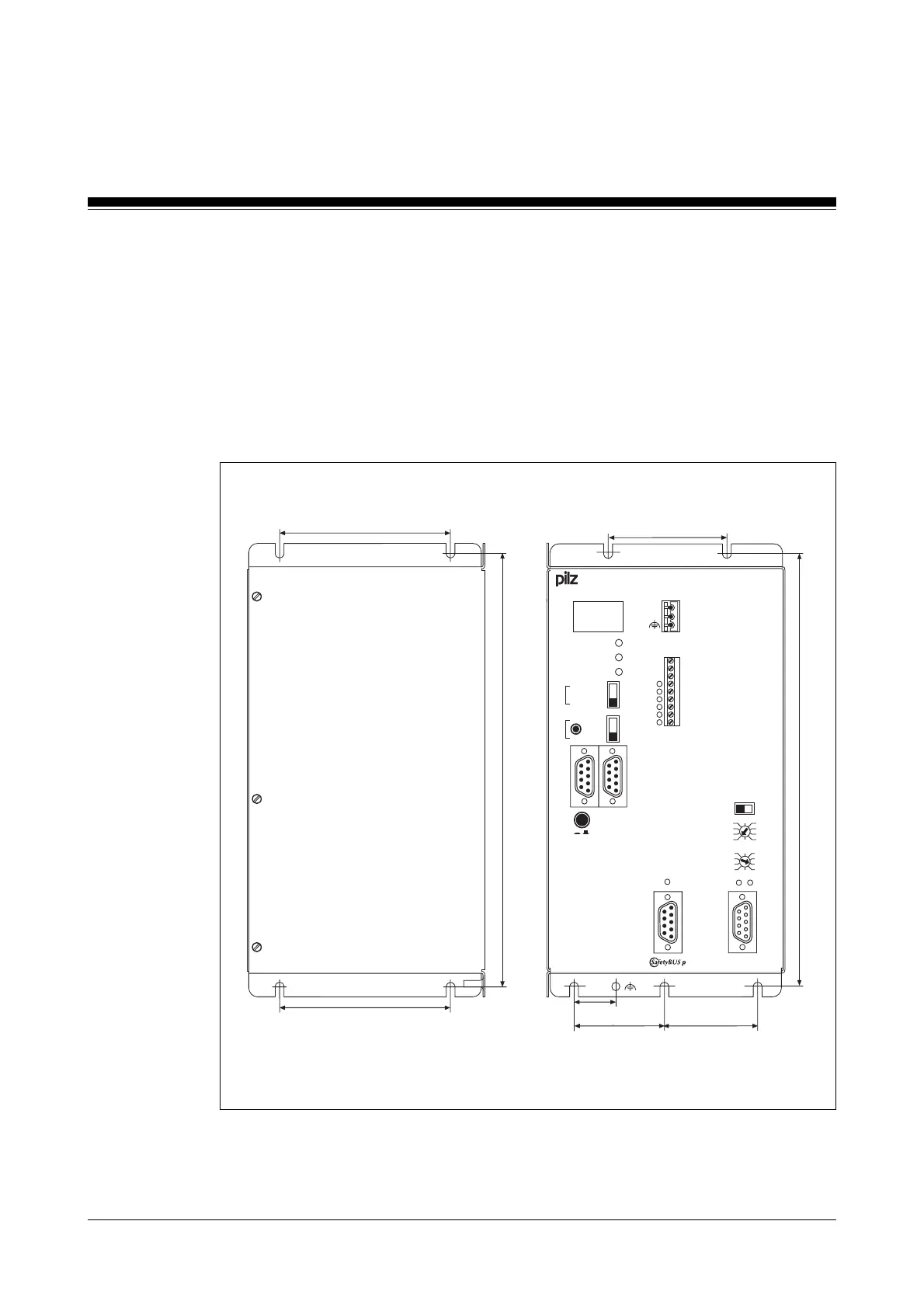
Fig. 5-1:
Options for installing safety systems from the PSS SB/SB2 3006-3 series
(example: PSS SB 3006-3 DP-S), dimensions stated in mm (")
RUN FS
RUN ST
POWER
PG
AUTO PG
SPS
ST
FS
+100 +0
x1
RUNFAULT
STOP
RUN
PROFIBUS-DP
ADDRESS
0 V
T 0
T 1
I 0.0
I 0.1
I 0.2
I 0.3
I 0.4
I 0.5
X1
1
.
.
.
.
.
.
9
x10
6
7
8
9
4
3
2
1
5
0
6
7
8
9
4
3
2
1
5
0
1
.
X0
.
3
PSS SB 3006-3 DP-S
ON
OFF
R
T
(USER)
PSS PWR
120 (4.72")
40 (1.58")
236,4 (9.31")
40 (1.58")
40 (1.58")
236,4 (9.31")
120 (4.72")
F-Stack
PG
Status SB
USER
24 V
0 V
20 (1.79")
Installing the safety system
There are two options for installing the safety system. Both are illustrated
in Fig. 5-1. Drill M5 or M6 holes in the control cabinet’s mounting plate, as
shown in Fig. 5-1 (tolerance: +/-0.3 mm/0.012"). You will require 4 holes.
Attach the safety system to the mounting plate in your control cabinet,
using washers.
Option A: Option B:
Dimensions in mm ("):
H x W x D: 246 x 123 x 161 (9.70" x 4.84" x 6.34")
Artisan Technology Group - Quality Instrumentation ... Guaranteed | (888) 88-SOURCE | www.artisantg.com

 Loading...