Supply Voltage
6-2 Operating Manual: PSS SB 3006-3 Series
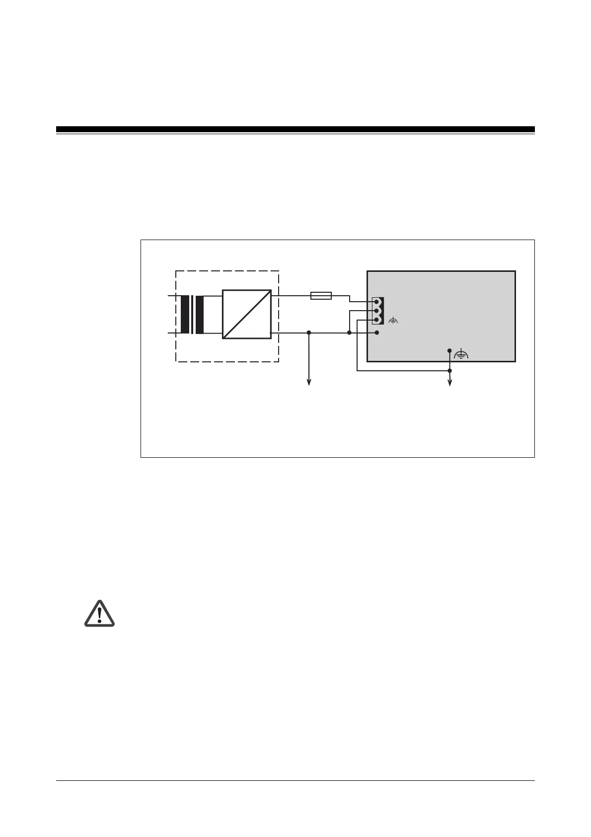
• Connecting the external power supply on programmable safety systems
without an INTERBUS interface
- The external power supply should be connected to the PSS as shown
in Fig. 6-1.
Fig. 6-1: Supplying programmable safety systems from the PSS SB 3006-3 series
~
=
L1
N
+24 V
0 V
X0
0 V X1
Connect to the central earth
bar in star form
Connect to the 0 V supply and
earth at a single point
External power supply
(PSS PWR)
PSS SB 3006-3
without INTERBUS interface
0 V
24 V
Functional earth
- The programmable safety system (“PSS PWR”) requires a 24 VDC
supply. Check that the voltage supplied from the external power supply
corresponds.
- The external 24 V supply must be able to provide a current of max.
550 mA plus load currents taken from the test pulse outputs and load
currents for SafetyBUS p fibre-optic couplers (25 mA per fibre-optic
coupler).
CAUTION!
The maximum permitted load current at connector X0 should not be
exceeded. Connector X0 should therefore be fused (see Fig. 6-1).
Artisan Technology Group - Quality Instrumentation ... Guaranteed | (888) 88-SOURCE | www.artisantg.com

 Loading...