3
5. OPERATING PROCEDURE
! Connect the leads to the input and place the wire-grip on the
circuit to be tested.
! Connect the probe to the oscilloscope with the insulated
BNC/BNC lead.
! Adjust the vertical zero adjustment of the oscilloscope if
necessary.
! Select the attenuation ratio* and the vertical deviation of the
oscilloscope in accordance with the conversion table below.
! NB: The POWER light must come on.
The conversion table gives the real vertical deviation.
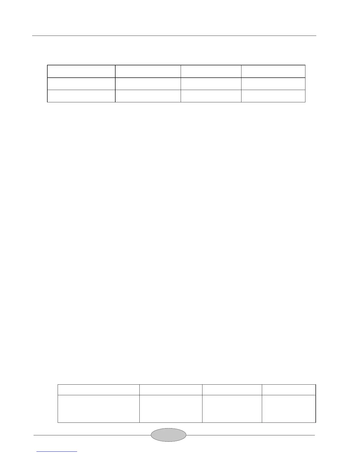
4. OPERATING ENVIRONMENTAL CONDITIONS
(1) Dimensions and Weight:
195 x 55 x 30 mm; 250g
(2) Electrical Safety to IEC 1010-1
! Dual Insulation
! Installation Category III
! Degree of Pollution 2
! Rated Voltage or Max Line-Earth: 600 Vrms
(3) CE Mark
Conforms to EN 50081-1 and 50082-1 standards
(4) Indoor use only.
DP-25 Instruction Manual
X 200 X 50 X 20
1400Vp-p 350Vp-p 140Vp-p
(±700VDC) (±175VDC) (±70VDC)
Voltage Input Range
(DC+AC Peak)
Attenuation
Temperature
Relative Humidity
Reference Use Storage
+20°C … +30°C
≦70 % RH
0°C … +50°C
10 % … 85 % RH
-30°C … +70°C
10 % … 90 % RH