Do you have a question about the Pioneer A-505R and is the answer not in the manual?
Details the procedure for adjusting idle current using specific components and measurements.
Details construction differences for specific A-605R and A-605R-G models.
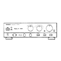
Details construction differences for specific A-505R models.
Details construction differences for specific A-405R and A-405R-G models.
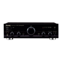
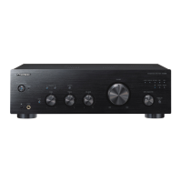
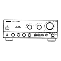
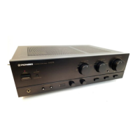
Explains the function and operation of various front panel controls, switches, and indicators.
The provided document is a service manual for the Pioneer A-605R, A-605R-G, A-505R, A-405R, and A-405R-G stereo amplifiers. This manual details the device's functions, technical specifications, usage features, and maintenance.
The Pioneer A-605R series are stereo amplifiers designed for audio entertainment systems. They serve as the central hub for various audio sources, amplifying signals for output to speakers. The core function of these amplifiers is to provide high-fidelity audio reproduction across multiple input types, including phono, CD, tuner, line, and tape.
The amplifiers boast robust power output capabilities. For the A-605R, continuous power output (both channels driven at 20 Hz to 20 kHz) is 60 W + 60 W at 8 Ω with a Total Harmonic Distortion (T.H.D.) of 0.06%, and 90 W + 90 W at 4 Ω with a T.H.D. of 0.09%. The A-405R offers slightly lower, but still substantial, power: 45 W + 45 W at 8 Ω (0.06% T.H.D.) and 65 W + 65 W at 4 Ω (0.09% T.H.D.). DIN continuous power output (both channels driven at 1 kHz) for the A-605R is 75 W + 75 W at 8 Ω (1.0% T.H.D.) and 120 W + 120 W at 4 Ω (1.0% T.H.D.). The A-405R provides 60 W + 60 W at 8 Ω (1.0% T.H.D.) and 90 W + 90 W at 4 Ω (1.0% T.H.D.). Dynamic power output (on EIA dynamic test signal) for the A-605R is 140 W/190 W (4 Ω/2 Ω), and for the A-405R, it is 100 W/115 W (4 Ω/2 Ω). The overall total harmonic distortion is remarkably low, at 0.05% (20 Hz to 20 kHz, 30 W, 8 Ω).
Input sensitivity and impedance vary by input type. The PHONO (MM) input has a sensitivity of 2.8 mV with 50 kΩ impedance. CD, TUNER, LINE, TAPE 1/DAT, and TAPE 2 MONITOR inputs all have a sensitivity of 200 mV with 50 kΩ impedance. The PHONO overload level (MM) is 150 mV at 1 kHz, 0.1% T.H.D. Output level and impedance for TAPE 1/DAT and TAPE 2 MONITOR outputs are 200 mV with 1 kΩ impedance.
The frequency response is tailored for audio fidelity. PHONO (MM) offers 20 Hz to 20 kHz ± 0.5 dB. CD, TUNER, LINE, TAPE 1/DAT, and TAPE 2 MONITOR inputs provide a wide 5 Hz to 150 kHz ± 3 dB response. Tone control features include BASS adjustment of ±8 dB at 100 Hz and TREBLE adjustment of ±8 dB at 10 kHz. The loudness contour (volume control set at -30 dB position) provides a boost of +5 dB at 100 Hz and +3 dB at 10 kHz.
Signal-to-Noise Ratio (IHF short circuit, A network) is excellent. For the A-605R, PHONO (MM, 5 mV input) is 88 dB, while CD, TUNER, LINE, TAPE 1/DAT, and TAPE 2 MONITOR inputs achieve 108 dB. The A-405R shows similar performance with 86 dB for PHONO (MM, 5 mV input) and 106 dB for other inputs. DIN Signal-to-Noise Ratio (continuous power/50 mW) for the A-605R is 71 dB/67 dB for PHONO (MM) and 95 dB/71 dB for other inputs. A MUTING function (volume control set at -30 dB position) is available for A-605R and A-505R only, providing a -20 dB reduction.
The amplifiers are designed for various power requirements, with models supporting AC 230 Volts, 50/60 Hz. Power consumption for the A-605R is 550 W, and for the A-405R, it is 380 W. Dimensions (including knobs and other protruding parts) are 420 (W) X 344 (D) × 132 (H) mm for the A-605R and 420 (W) X 344 (D) × 125 (H) mm for the A-405R. Weight (without package) is 6.6 kg for the A-605R and 6.5 kg for the A-405R.
The front panel of the amplifier provides intuitive controls for various functions. The POWER STANDBY/ON switch/indicator controls the main power. When ON, power is supplied, and the unit is operational. In STANDBY, main power flow is cut, but a minute flow maintains operation readiness, indicated by the STANDBY light. This is particularly useful for timer recording.
The Remote control sensor window allows for operation via a remote control unit. A large VOLUME control knob adjusts the sound level, with the TONE effect remaining active regardless of volume levels.
The INPUT SELECTOR knob/indicators allow users to choose their desired audio source (CD, TUNER, PHONO, LINE, TAPE 1/DAT). Turning the knob clockwise or counterclockwise illuminates the corresponding indicator.
The TAPE 2 MONITOR button/indicator is used when an adaptor component (e.g., graphic equalizer) or cassette deck is connected to the TAPE 2 MONITOR terminals. When ON, the indicator lights, and the signal from the connected component is monitored. It is crucial to set this switch to OFF when not in use or when no connections are made to avoid sound issues.
The DIRECT button/indicator bypasses various frequency adjusting circuits (BASS, TREBLE, BALANCE, LOUDNESS) for a flat, pure sound reproduction, ensuring a more faithful reproduction of the input source. When ON, the indicator lights, and signals are reproduced without passing through these circuits.
The REC SELECTOR switch (for TAPE 1/DAT terminals) allows for recording from selected equipment, independent of the INPUT SELECTOR knob and DIRECT button settings. Options include SOURCE (records from the currently selected input), OFF (disconnects the cassette deck for improved sound quality), CD, and TUNER.
A BALANCE control adjusts the sound balance between the left and right speakers. It should normally be left in the center position.
The MUTING button/indicator (A-605R and A-505R only) temporarily lowers the sound volume by 20 dB, indicated by a flashing VOLUME indicator.
The LOUDNESS button/indicator boosts low and high frequencies at low volume levels for added punch.
Tone controls for TREBLE and BASS allow for adjustment of high and low frequencies, respectively. The center position is flat (normal). These controls do not operate when the DIRECT button is ON.
SPEAKERS A and B selector buttons/indicators allow users to select which speaker system (connected to SPEAKERS A or B terminals) to use.
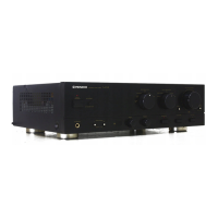
A PHONES jack is provided for connecting headphones.
The rear panel offers a comprehensive set of connections: PHONO terminals for turntables, a GND (Turntable ground) terminal, TUNER terminals, CD terminals, and LINE terminals. TAPE 1/DAT REC and PLAY terminals for connecting a cassette deck or digital audio cassette. TAPE 2 MONITOR REC (OUT) and PLAY (IN) terminals for connecting an adaptor component or a second tape deck. SPEAKERS B and A terminals (Right and Left channels) for connecting speaker systems. VOLTAGE SELECTORS (for multi-voltage models) allow adjustment for different regional power supplies. AC OUTLETS (SWITCHED and UNSWITCHED) provide power for other audio components. A caution advises against connecting a monitor or TV set to these outlets. An AC INLET jack connects the power cord to the unit. A CONTROL OUT jack outputs control signals for operating other Pioneer components with the amplifier's remote control unit.
The manual provides clear instructions for maintaining the external surfaces of the amplifier. To clean off dust and dirt, a polishing cloth or dry cloth should be used. For very dirty surfaces, a soft cloth dipped in a neutral cleanser diluted with water, wrung out well, and then wiped with a dry cloth is recommended. Users are cautioned against using furniture wax, cleaners, thinners, benzine, insecticide sprays, or other chemicals, as these can corrode the surfaces.
The manual also includes detailed exploded views and parts lists, schematic and PCB connection diagrams, PCB parts lists, adjustment procedures (e.g., Idle Current Adjustment), IC information, and a block diagram, all crucial for service and repair. The idle current adjustment procedure involves connecting a DC voltmeter to specific points (R413 or R414) and adjusting VR301 (VR302) to achieve a target voltage of 16mV±1mV initially, followed by aging for 7 minutes, and then readjusting to 11mV±1mV. This ensures optimal performance and longevity of the amplifier.