EasyManua.ls Logo

Pioneer A-509R Service Manual

Pioneer A-509R
30 pages
To Next Page IconTo Next Page
Page #1 background imageLoading...
Page #1 background image
ORDER NO.
PIONEER CORPORATION 4-1, Meguro 1-chome, Meguro-ku, Tokyo 153-8654, Japan
PIONEER ELECTRONICS SERVICE, INC. P.O. Box 1760, Long Beach, CA 90801-1760, U.S.A.
PIONEER EUROPE N.V. Haven 1087, Keetberglaan 1, 9120 Melsele, Belgium
PIONEER ELECTRONICS ASIACENTRE PTE. LTD. 253 Alexandra Road, #04-01, Singapore 159936
PIONEER CORPORATION 2000
c
RRV2285
1. SAFETY INFORMATION
......................................
2
2. EXPLODED VIEWS AND PARTS LIST
...............
3
3. BLOCK DIAGRAM AND SCHEMATIC DIAGRAM
.....
6
4. PCB CONNECTION DIAGRAM
.........................
16
5. PCB PARTS LIST
...............................................
21
6. ADJUSTMENT
....................................................
24
CONTENTS
7. GENERAL INFORMATION
................................
25
7.1 IC
..................................................................
25
8. PANEL FACILITIES AND SPECIFICATIONS
.......
26
T – ZZK APR. 2000 Printed in Japan
THIS MANUAL IS APPLICABLE TO THE FOLLOWING MODEL(S) AND TYPE(S).
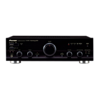
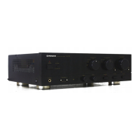
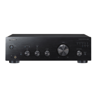
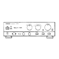
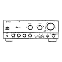
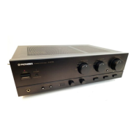
STEREO AMPLIFIER
A-509R Direct Energy MOS
STANDBY/ON
STANDBY
OFF ON
POWER
A SPEAKERS B BASS TREBLE
PHONES
LOUDNESS
MIN MAX
VOLUME
DIRECT/
SB MODE
BALANCE INPUT SELECTOR REC SELECTOR
CD TUNER PHONO
TAPE 1/
CD-R/MD
LINE/
SB
TAPE 2
MONITOR
CD TUNER
OFF SOURCE
L R
STEREO AMPLIFIER
A-509R
Type
Model
Power Requirement Remarks
A-509R
MY AC220-230V

Other manuals for Pioneer A-509R

Questions and Answers:

Pioneer A-509R Specifications

Amplifier Section IconAmplifier Section
continuous power output (20 Hz to 20 kHz, 8 Ω)45 W + 45 W
continuous power output (20 Hz to 20 kHz, 4 Ω)65 W + 65 W
DIN continuous power output (1 kHz, 8 Ω)60 W + 60 W
DIN continuous power output (1 kHz, 4 Ω)90 W + 90 W
total harmonic distortion (20 Hz to 20 kHz, 20 W, 8 Ω)0.05 %
input sensitivity/impedance (PHONO MM)2.8 mV/50 kΩ
input sensitivity/impedance (CD, TUNER, LINE/SB, TAPE 1/CD-R/MD, TAPE 2 MONITOR)200 mV/50 kΩ
PHONO (MM) overload level (1 kHz, T.H.D. 0.1 %)150 mV
output level/impedance (TAPE 1/CD-R/MD, TAPE 2 MONITOR)200 mV/1 kΩ
frequency response (PHONO MM)20 Hz to 20 kHz ± 0.5 dB
frequency response (CD, TUNER, LINE/SB, TAPE 1/CD-R/MD, TAPE 2 MONITOR)5 Hz to 100 kHz +0-3 dB
tone control (BASS)± 8 dB (100 Hz)
tone control (TREBLE)± 8 dB (10 kHz)
loudness contour (volume control set at – 30 dB position)+ 5 dB (100 Hz)/ + 3 dB (10 kHz)
signal-to-noise ratio (PHONO MM, 5 mV input)86 dB
signal-to-noise ratio (CD, TUNER, LINE/SB, TAPE 1/CD-R/MD, TAPE 2 MONITOR)106 dB
signal-to-noise ratio (DIN, continuous power/ 50 mW, PHONO MM)71 dB/ 67 dB
signal-to-noise ratio (DIN, continuous power/ 50 mW, CD, TUNER, LINE/SB, TAPE 1/CD-R/MD, TAPE 2 MONITOR)95 dB/ 71 dB
Power Supply IconPower Supply
power requirementsAC 220 - 230 V, 50/60 Hz
power consumption160 W
power consumption in standby mode1 W
AC outlet switched100 W
Weight and Dimensions IconWeight and Dimensions
dimensions (including knobs and other protruding parts)420 (W) x 335 (D) x 128 (H) mm
weight (without package)6.9 kg

Summary

Safety Information

Safety Precautions

Essential safety checks for technicians and customers.

Product Safety Notice

Identifies critical safety components and their importance.

Exploded Views and Parts List

Packing Details

Lists all components included in the product packaging.

Exterior View

Illustrates the external physical components and their arrangement.

Block Diagrams and Schematics

Block Diagram

Visual overview of the amplifier's functional blocks and signal flow.

Overall Connection Diagram

Shows how different internal assemblies connect to each other.

AF Assembly Schematic

Detailed schematic of the Audio Frequency amplifier section.

Front L and Volume Assembly Schematics

Schematics for front left and volume control circuits.

Front R, AC Primary, Headphone, and Power SW Schematics

Schematics for front right, power supply, and headphone modules.

PCB Connection Diagrams

AF Assembly PCB Layout

Physical layout and component placement for the AF amplifier board.

Front L and Volume Assembly PCB Layouts

PCB layout for front left and volume control assemblies.

Front R Assembly PCB Layout

PCB layout for the front right amplifier board.

AC Primary, Headphone, and Power SW PCB Layouts

PCB layouts for AC primary, headphone, and power switch modules.

PCB Parts List

Adjustments

Idle Current Adjustment

Procedure for setting the amplifier's idle current for optimal performance.

General Information

Integrated Circuit (IC) Details

Information on the functions and pin assignments of key ICs.

Panel Features and Specifications

Front Panel Controls and Indicators

Description of all controls, buttons, and indicators on the front panel.

Rear Panel Connections

Identification and explanation of all input/output terminals on the rear panel.

Remote Control Operation

Guide to operating the amplifier using the included remote control.

Technical Specifications

Detailed technical specifications including power, sensitivity, and frequency response.

Related product manuals