Do you have a question about the Pioneer A-90 and is the answer not in the manual?
Includes power switch, bass/treble controls, and turnover frequency selection.
Manages stereo/mono modes, speaker output, and headphone jack.
Selects input sources, tape monitoring, and copy functions.
Explains muting, line straight, subsonic filter, and balance operations.
Covers MC Head Amplifier and Equalizer Amplifier circuits.
Details Tone Control and Phono System Muting circuits.
Explains Line Straight, Power Amplifier, and Protector circuits.
Describes the variable voltage power supply system.
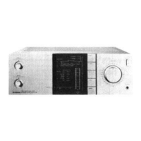
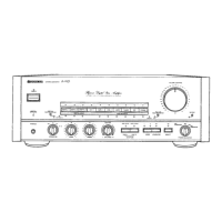
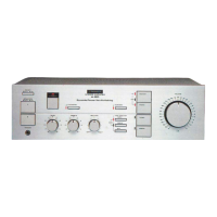
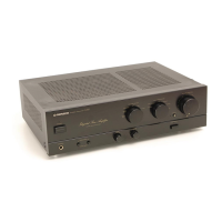
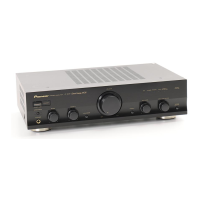
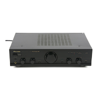
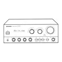
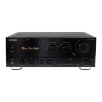
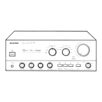
Identifies parts on the front panel and view.
Locates parts on top, bottom, and rear views.
Exploded view of external parts.
Exploded view and parts list for the front panel.
Lists miscellaneous, PCB, switches, and other parts.
Lists parts for regulator and left power amp.
Lists parts for tone, muting, mode, headphone controls.
Lists parts for function, terminals, tone, volume, protection, rectifier, output.
Lists parts for right power amp and AF assembly.
Procedure to set idle current for optimal performance.
Essential checks for customer and technician safety.
Information on critical safety-related components.
| Type | Integrated Amplifier |
|---|---|
| Signal-to-Noise Ratio | 110dB (IHF-A) |
| Input Impedance | 47 kΩ |
| Input sensitivity | 150mV |
| Frequency Response | 5Hz-100kHz (+0dB, -3dB) |
| Total Harmonic Distortion (THD) | 0.005% |
| Dimensions | 420 x 177 x 464 mm (W x H x D) |
| Speaker load impedance | 4Ω-16Ω |
| Output Power | 100W + 100W (8Ω, 20Hz-20kHz, THD 0.05%) |