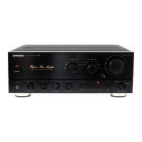
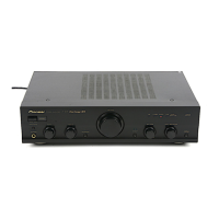
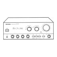
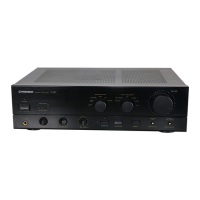
Do you have a question about the Pioneer A-91D and is the answer not in the manual?
General precautions for continued protection of customer and technician.
Procedure to measure leakage current to earth ground, max 0.5mA.
Highlights safety characteristics of parts and risks of using substitutes.
List of external parts with part numbers and descriptions.
List of packing materials including pads, case, and instructions.
Diagram of the digital signal processing and interface sections.
Details on input/output circuits for digital audio data conversion.
Explains CMOS logic ICs for input function changeover and REC selection.
Circuit to compensate for signal pulse width distortion during optical transmission.
Lists general electronic components like resistors, capacitors, semiconductors, etc.
Detailed list of capacitors with part numbers and descriptions.
Detailed list of transistors and ICs with part numbers.
List of coils with part numbers and descriptions.
Detailed list of resistors with part numbers and descriptions.
Overview of digital circuit operations, including optical transmission and I/O.
Function of optical fiber connectors converting signals between electrical and optical.
Description of input/output circuits for digital audio data, including buffers.
Details on CMOS logic ICs for function selection, REC selection, and ADPT ON/OFF.
Circuit designed to correct signal distortion during optical transmission.
Explains the 4x over-sampling digital filter and its input signals.
Circuit for muting data when PLL1 is unlocked, preventing noise.
Describes D/A conversion using IC301/IC302 and MSB adjustment.
Amplifier converting current output to voltage, requiring level adjustment.
Filter circuit allowing specific frequencies to pass, affecting amplifier noise.
Circuit with buffer amplifier and de-emphasis for CD software pre-emphasis.
Pin arrangement, operation, and digital audio data timing for the CXD1076P IC.
Timing details for LRCK, DATA, BCK, WCK signals and data output.
Visual representation of timing signals for the CXD1076P.
Internal circuit diagram and pin description for the SN74LS624N IC.
Pin description for the YM3404B IC.
Pin description and grading information for the PCM56P IC.
Internal circuit diagram for the SN74ALS163BN IC.
Procedure to adjust PLL for fs 32kHz to 48kHz range, ensuring proper sound.
Procedure to correct MSB bit current dispersion and minimize distortion.
Details differences in miscellaneous parts for HB, HEZ, SD/G types compared to KU/CA.
Wiring diagram and part differences for HB and HEZ models.
Wiring diagram and part differences for SD/G models.