Do you have a question about the Pioneer A-A9-J and is the answer not in the manual?
Outlines essential safety measures for technicians and customers, including notices for specific models and warnings.
Provides caution and instructions for safe lithium battery handling and replacement to prevent hazards.
Ensures adherence to product regulations and maintains a safe servicing environment by following instructions.
Details maintaining original product performance through proper adjustments, lubricants, and part replacements.
Describes proper cleaning for components and instructions for setting shipping mode to prevent transit damage.
Details amplifier power output, distortion, audio input/output characteristics, and frequency response.
Includes power requirements, consumption, weight, and physical dimensions of the unit.
Provides visual breakdown and part numbers for the A-A9 model, including packing and exterior components.
Provides visual breakdown and part numbers for the A-A6 model, including packing and exterior components.
High-level functional overview of the amplifier's internal architecture and signal flow.
Illustrates the interconnections between various internal assemblies and connectors.
Detailed schematics for the main audio amplifier channels (LCH/RCH) and protection circuits.
Schematics for voltage regulators, power supply, and switching components.
PCB layout for the sub-transformer and power switching assemblies.
PCB layout for the function and headphone amplifier circuits.
PCB layouts for front panel components, remote control, and VR assemblies.
PCB layouts for station selection and motor VR assemblies.
PCB layout for the XM-Ready and USB interface circuitry.
PCB layout for the left channel amplifier and protection circuits.
PCB layout for the right channel amplifier and protection circuits.
PCB layouts for voltage regulators and power supply units.
Catalog of main assemblies with their corresponding part numbers for A-A9 and A-A6 models.
Highlights differences in PCB construction for specific assemblies between models.
Procedures for adjusting idle current and DC offset for optimal amplifier performance.
Provides guidance for diagnosing and resolving common operational issues.
Details the amplifier's protective modes, such as overload and DC detection.
Safety procedure for safely discharging power amplifier capacitors before service.
Visual guide showing the physical placement of major PCBs within the unit.
Step-by-step instructions for disassembling the A-A6 and A-A9 models.
Details on integrated circuits, including pin functions and microcomputer information.
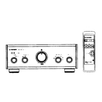
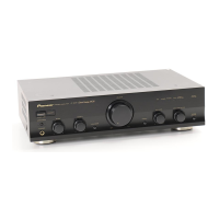
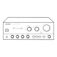
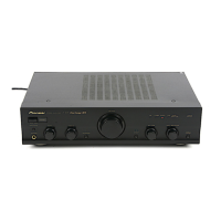
Identifies and describes the functions of front panel buttons, displays, and jacks.
Explains the functions of the remote control buttons for amplifier operation.
Describes the meaning of indicators and controls shown on the unit's display.
| Impedance | 4 Ω |
|---|---|
| Frequency range | 20 - 100000 Hz |
| RMS rated power | 110 W |
| Signal-to-Noise Ratio (SNR) | 103 dB |
| Total Harmonic Distortion (THD) | 0.2 % |
| Output power | 70 W |
| Channels quantity | 2 channels |
| Dimensions (WxDxH) | 420 x 369 x 113 mm |
| Power requirements | 220 - 230 V, 50/60 Hz |
| Headphone outputs | 1 |
| Product color | Black |
| Power consumption (standby) | 0.6 W |
| Power consumption (typical) | 200 W |
| Weight | 11500 g |
|---|