Do you have a question about the Pioneer CT-S520 and is the answer not in the manual?
General safety precautions for technicians and users.
Procedure to measure leakage current for safety.
Important safety related characteristics of replacement parts.
List of parts and their corresponding part numbers for packing.
Exploded view and parts list for external components.
Exploded view of the mechanism unit.
Procedure for tape speed adjustment.
Adjusting the head azimuth for optimal playback.
Setting playback level for Dolby NR and HX Pro.
Adjusting the bias oscillator frequency.
Adjusting the bias trap for minimum output.
Adjusting recording bias for distortion rate.
Setting recording level for different tape types.
Performing automatic bias and level adjustment.
Pin functions for the PD4443A CPU.
Pin assignment and functions for NM93C46N memory.
Pin functions for LC7570 BLE data conversion IC.
| Track System | 4-track, 2-channel stereo |
|---|---|
| Number of Heads | 3 |
| Heads | 1 x record, 1 x playback, 1 x erase |
| Tape Type | type I, CrO2, Metal |
| Total Harmonic Distortion | 0.8% |
| Output | 0.5V (line) |
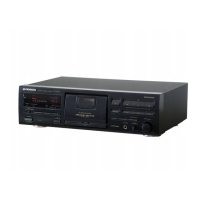
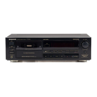
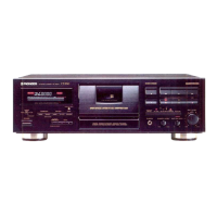
| Type | single compact cassette deck |
| Motor | 1 x reel, 1 x capstan |
| Inputs | Line In |
| Outputs | Line Out |