Do you have a question about the Pioneer CT-W806DR and is the answer not in the manual?
General safety measures for technicians and users.
Information on safety-related characteristics of parts.
Exploded view of packing, parts list, and contrast table.
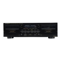
Exploded view of the unit's exterior components.
Exploded view of the front panel and its components.
Exploded view of the tape mechanism unit and its parts.
High-level block diagram of the unit's circuitry.
Detailed schematics for the Main Unit across pages 11-13.
Schematic diagram for the Main Unit, part 4.
Schematics for Motor, POC, and Timer Units.
Diagrams showing PCB connections for various units.
PCB layouts for Motor, POC, Timer, and TRN units.
PCB layout for the Subb Unit.
PCB layout for the Core Unit.
PCB layouts for Dir and Jack Units.
Table listing PCB assemblies and their part numbers for different models.
Details on construction differences between PCB assemblies.
Procedures for mechanical adjustments, focusing on tape speed.
Procedures for electrical adjustments, including playback and recording sections.
Pin function details for specific ICs used in the unit.
Information about the FL tube display, pin assignments, and connections.
Procedures for entering, exiting, and operating various test modes.
Overall functional block diagram of the audio signal path.
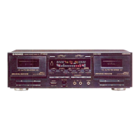
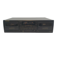
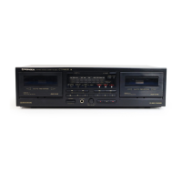
Description and location of front panel controls and indicators.
Technical specifications of the CT-W806DR/CT-07D unit.
| Brand | Pioneer |
|---|---|
| Model | CT-W806DR |
| Category | Cassette Player |
| Language | English |