EasyManua.ls Logo

Pioneer CX-J500 User Manual

Pioneer CX-J500
35 pages
To Next Page IconTo Next Page
Page #1 background imageLoading...
Page #1 background image
Y
PIONEER
The
Art
of
Entertainment
TUNER
CONTROL
AMPLIFIER
AMPLIFICATEUR
DE
COMMANDE
TUNER
PRT
DE
TR
Operating
Instructions
Mode
d’emploi
CX-J300/CX-J400*/CxX-J500**
STEREO
POWER
AMPLIFIER
AMPLIFICATEUR
DE
PUISSANCE
STEREO
Mi-
J200/M-J300
SOUND
IMAGE
CONTROLLER
CONTROLEUR
D‘IMAGE
SONORE
GR-J300/GR-J400
STEREO
DOUBLE
CASSETTE
TAPE
DECK
DOUBLE
PLATINE
CASSETTE
STEREO
CT-J200WR/CT-J3Z00WR
.
AUTO-RETURN
STEREO
TURNTABLE
TABLE
DE
LECTURE
STEREO
A
RETOUR
AUTOMATIQUE
PL-J400/PL-J500
*
The
CX-J400
is
for
Europe
only.
**
The
CX-J500
is
sold
outside
U.K.,
Europe,
and
Australia.
WARNING:
To
PREVENT
FIRE
OR
SHOCK
HAZARD,
DO
NOT
EXPOSE
THIS
APPLIANCE
TO
RAIN
OR
MOISTURE.
FM/AM
CHANNEL
SWITCH
This
switch
is
not
provided
on
models
for
Europe,
U.K.
or
Australia.
switch
at
the
rear
panel
on
the
tuner
contro!
amplifier.
The
CHANNEL
STEP
switch
is
located
on
the
rear
panel
of
the
tuner
control
arnolifier.
Before
the
tuner
contro!
amplifier
leaves
the
factory,
this
switch
is
set
to
the
channel
step
standard
of
the
area
where
the
tuner
control
amplifier
is
sold.
Depending
on
the
position
of
this
switch,
each
time
TUNING
button
is
pressed,
the
frequency
display
changes
by
the
following
amount:
1100
kHz/10
kHz]
position
For
areas
with
channel
step
of
100
kHz
for
FM
and
10
kHz
for
AM.
{50
kH2z/9
kHz}
position
For
areas
with
channel
step
of
50
kHz
for
FM
and
9
kHz
for
AM.
NOTE:
If
the
switch
is
set
to
the
wrong
position,
correct
tuning
may
not
be
possible.
Consult
your
dealer
if
you
are
not
sure
about
the
radio
channel
step
standard
in
your
area.
Adjustment
is
only
necessary
when
there
is
a
CHANNEL
STEP
j
English
Francais
*
Le
modéle
CX-J400
n‘est
destiné
qu’a
Europe.
**
Le
modéle
CX-J500
est
vendu
a
I’extérieur
du
Royaume-Uni,
de
Europe
et
de
I'Ausiralie.
(For
tuner
control
amplifier
and
stereo
power
amplifier)
LINE
VOLTAGE
SELECTOR
SWITCH
Only
multi
voltage
models
are
provided
with
this
switch.
European,
U.K.,
and
Australian
models
are
not
provided
with
this
switch.
Mains
voltages
in
Saudi
Arabia
are
127
V
and
220
V
only,
Never
use
this
model
with
110
V
setting
in
Saudi
Arabia.
Before
your
model
is
shipped
from
the
factory,
this
switch
is
set
to
the
power
requirements
of
the
destination;
nevertheless,
you
should
check
that
it
is
set
properly
before
plugging
the
power
cord
into
the
AC
outlet.
1.
Disconnect
the
power
cord.
2.
Use
a
medium-size
screwdriver.
3.
Insert
the
screwdriver
into
the
groove
on
the
voltage
selector
and
adjust
so
that
the
voltage
value
of
your
area.
20v
zaov
Ov
120v—1270

Other manuals for Pioneer CX-J500

Question and Answer IconNeed help?

Do you have a question about the Pioneer CX-J500 and is the answer not in the manual?

Pioneer CX-J500 Specifications

General IconGeneral
BrandPioneer
ModelCX-J500
CategoryAmplifier
LanguageEnglish

Summary

Operating Instructions and Safety

General Safety Warning: Rain and Moisture

Do not expose the appliance to rain or moisture to prevent fire or shock hazard.

FM/AM Channel Switch Operation

Details on the FM/AM channel switch for tuner control amplifier operation.

Line Voltage Selector Switch

Instructions for setting the line voltage selector switch for multi-voltage models.

Before Operating the Unit

Confirm Supplied Accessories

List of accessories supplied with the Pioneer product for confirmation.

Loading Batteries into Remote Control Unit

Instructions for correctly loading batteries into the remote control unit.

Basic Connections and Rear Panel Overview

Component Connection Diagram

Diagram illustrating basic connections between system components.

Power Cord Connection Safety

Precautions for connecting the power cord to the AC wall socket.

Surround System Operation (M-J300)

Understanding Surround Sound

Explanation of surround sound and its effects on audio experience.

Stereo Wide Functionality

Description of the Stereo Wide function for enhanced stereo effects.

Speaker System Placement Examples

Examples of speaker placement for optimal surround sound effects.

Turntable Setup and Installation

Checking Turntable Parts

Ensuring all necessary parts for the turntable setup are present.

Turntable Installation Steps

Step-by-step guide for installing the PL-J400/PL-J500 turntable.

Antenna Connections

Importance of Proper Antenna Connection

Explains why correct antenna connection is vital for good radio reception.

FM Antenna Attachment and Installation

Instructions for attaching the accessory FM antenna and installing an external FM antenna.

Rear Panel Connections and Components

Rear Panel Jack and Outlet Descriptions

Description of AC outlets, tape deck, and sound image controller jacks.

Power Amplifier Speaker Terminals

Instructions for connecting speakers to the power amplifier.

Sound Image Controller Rear Panel

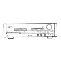
Description of rear panel connections for the Sound Image Controller.

Cassette Tape Deck Rear Panel

Description of rear panel connections for the Stereo Double Cassette Deck.

Front Panel Controls and Display

Memory Scan Button Function

Operation of the memory scan button for preset stations.

Function Button and Indicators

Using the function button to select input sources and understanding indicators.

Front Panel Display Indicators

Explanation of the various indicators shown on the display section.

Front Panel Controls for Amplifier and Controller

Stereo Power Amplifier Front Controls

Description of PHONES jack, power switch, and speaker buttons on the amplifier.

Sound Image Controller Front Controls

Operation of display, mode, and effect selection buttons on the controller.

Additional Front Panel Operations

Sound Image Controller Memory and EQ

Using MEMORY, SMART EQ, and EFFECT buttons for sound control.

Double Cassette Deck Operation Buttons

Instructions for operating the PLAY, STOP, and other buttons on the cassette deck.

Front Panel Display and Dolby NR Controls

Cassette Deck Display Section

Explanation of indicators and displays on the cassette deck.

Dolby NR Switch Operation

How to use the Dolby NR switch for noise reduction on cassette decks.

Front Panel Controls for CD, Decks, and Tuner

CD Player Operation Buttons

Controls for CD playback, random, and programmed modes.

Deck I Operation and Tuner/CD Select Switch

Operation of Deck I buttons and the TUNER/CD select switch.

Sound Image Control Buttons

Using VOLUME, SURR & ST.WIDE, and sound image control buttons.

Additional Front Panel Controls and Remote Operation

CD, Deck, Timer, and Station Control Buttons

Controls for CD, deck operations, timers, and station tuning.

Remote Control Operation Range

Specifications for the effective range and angle of the remote control.

Cassette Tape Handling and Usage Tips

Proper Cassette Installation

Points to consider before installing a cassette into the player.

Using Erasure Protection Tabs

Explanation of the function of cassette protection tabs.

Cassette Usage Recommendations

Advice on cassette handling, storage, and type selection.

Basic Tuner Operations

Tuner Operation Overview

How to operate the tuner control amplifier.

Tuning into Radio Stations

Instructions for manual and auto tuning to radio stations.

Preset Tuning Operations

Manual Preset Station Memorization

Step-by-step guide to memorizing stations manually.

Receiving with Preset Tuning

How to receive stations using the preset tuning feature.

Cassette Deck Playback Operations

Playing Tapes on Deck I or II

Instructions for playing tapes in Deck I or Deck II, including reverse mode.

Auto Stop and Blank Skip Features

Explanation of the auto stop mechanism and blank skip function.

Recording Operations and Features

Recording Source Selection and Setup

Selecting sources and setting up for recording.

Automatic Tape Selector and Reverse

How the automatic tape selector and auto reverse functions work.

Recording Level Adjustment

Adjusting recording level for optimal sound quality.

Dolby HX PRO and Tape Relay Playback

Dolby HX PRO Headroom Extension

Explanation of the Dolby HX PRO system for improved recording.

Cassette Tape Relay Playback Guide

Instructions for performing relay playback between cassette decks.

Cassette Tape Copying Guide

Tape Copying Procedure

Steps for copying recorded contents from one tape to another.

Synchro Copy Functionality

Using NORM and HIGH speed synchro copy modes.

Auto Synchro Editing System (A.S.E.S.)

NORM EDIT Procedure

Steps for using the NORM EDIT function of the A.S.E.S.

Linked A.S.E.S. Recording

How to continue A.S.E.S. recording with additional CDs.

A.S.E.S. Fine Editing

FINE EDIT Procedure

Steps for using the FINE EDIT function of the A.S.E.S.

Setting Recording Time for A.S.E.S.

How to specify recording time for A.S.E.S. using number buttons.

Sound Image Control Functions

Understanding Sound Image Control

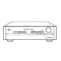
Explanation of sound image control and its available settings.

Operating Sound Image Controls

Using EFFECT, SFC MODE, and image effect buttons.

Record Mode Equalization Settings

Selecting equalization for car stereo or headphone stereo recordings.

Memorizing and Recalling Sound Images

Memorizing Custom Sound Images

Steps to create and memorize your own sound field images.

Recalling Memorized Sound Images

How to recall previously memorized sound images.

Surround and Stereo Wide Operation

Smart Equalizer Functionality

Automatic equalization adjustment for sound field and source.

Activating Surround and Stereo Wide

Instructions for activating Surround and Stereo Wide modes.

Timer Playback Setup

Timer Playback Source Selection

Selecting the source (CD, Tape, Radio) for timer playback.

Setting Timer Playback Time

Steps for setting the start time and selecting timer playback.

Timer Recording Setup

Preparing for Timer Recording

Inserting tape and setting Dolby NR/Reverse Mode for recording.

Setting Timer Recording Time

Steps for setting the REC timer selector button.

Maintenance Procedures

Cleaning the Head Section

Instructions for cleaning the tape heads, capstan, and pinch roller.

Demagnetizing the Head

Procedure for demagnetizing the recording/playback head.

Troubleshooting Common Issues

Power and Sound Issues

Solutions for no power, no sound, or one-sided sound.

Cassette Deck Function Problems

Troubleshooting for deck door, tape running, and sound issues.

Recording and Copying Problems

Solutions for recording failure, residual sound, and copy issues.

Sound Quality and Abnormal Sound Issues

Addressing muddy sound, high frequencies, and humming.

Advanced Troubleshooting

Clock, Timer, and Remote Control Issues

Solutions for clock, timer, and remote control malfunctions.

Disc Player and Turntable Problems

Troubleshooting for CD player and turntable operational faults.

Troubleshooting: Cassette Deck and General Issues

Cassette Deck Operation Faults

Resolving issues with cassette deck door, tape movement, and sound.

Recording and Copying Fault Diagnosis

Troubleshooting for recording, residual sound, and tape copying errors.

Sound Quality and Interference Issues

Addressing sound issues like muddiness, high frequencies, and interference.

Technical Specifications

Power Amplifier Specifications

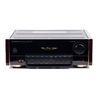
Technical details for the M-J200/M-J300 power amplifier.

Tuner Control Amplifier Specifications

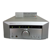
Technical details for the CX-J300/CX-J400/CX-J500 tuner control amplifier.

Power Cord Safety Precautions

Handling the Power Cord Safely

Instructions for safely handling and maintaining the power cord.

Related product manuals