EasyManua.ls Logo

Pioneer C-90 User Manual

Pioneer C-90
48 pages
To Next Page IconTo Next Page
Page #1 background imageLoading...
Page #1 background image
Operating
Instructions
Bedienungsanleitung
STEREO
CONTROL
AMPLIFIER
STEREO-STEUERVERSTARKER
Ss
is
AMPLIFICATEUR
DE
CONTROLE
STEREO
AMPLIFICATORE
DI
CONTROLLO
STEREO
Cc-90
Mode
d’emploi
Istruzioni
per
uso
Thank
you
for
buying
this
Pioneer
product.
Please
read
through
these
operating
instructions
so
you
will
know
how
to
operate
your
model
properly.
After
you
have
finished
reading
the
instructions,
put
them
away
in
a
safe
place
for
future
reference.
In
some
countries
or
regions,
the
shape
of
the
power
plug
and
power
outlet
may
sometimes
differ
from
that
shown
in
the
ex-
planatory
drawings.
However,
the
method
of
connecting
and
operating
the
unit
is
the
same.
WARNING:
To
prevENT
FIRE
OR
SHOCK
HAZARD,
DO
NOT
EXPOSE
THIS
APPLIANCE
TO
RAIN
OR
MOISTURE.
IMPORTANT
NOTICE
{For
U.S.
and
Canadian
models]
The
serial
number
for
this
equipment
is
located
o.
we
rear
panel.
Please
write
this
serial
number
on
your
enclosed
war-
ranty
card
and
keep
it
in
a
secure
area.
This
is
for
your
securi-
ty.
[For
Canadian
model]
CAUTION:
to
prevENT
ELECTRIC
SHOCK
DO
NOT
USE
THIS
(POLARIZED)
PLUG
WITH
AN
EXTENSION
CORD,
RECEPTACLE
OR
OTHER
OUTLET
UNLESS
THE
BLADES
CAN
Medium-size
screwdriver
a)
BE
FULLY
INSERTED
TO
PREVENT
BLADE
EXPOSURE.
a
SPs
xv
oe
=<
ATTENTION:
pour
prevenir
Les
CHOCS
ELEC-
Set
the
voltage
selector
switch
for
the
voltage
in
your
area.
[ium]
TRIQUES
NE
PAS
UTILISER
CETTE
FICHE
POLARISEE
AVEC
Pd
UN
PROLONGATEUR
UNE
PRISE
DE
COURANT
OU
UNE
ap
_
AUTRE
SORTIE
DE
COURANT,
SAUF
SI
LES
LAMES
PEUVENT
ey
ETRE
INSEREES
A
FOND
SANS
EN
LAISSER
AUCUNE
PARTIE
A
DECOUVERT.
L
110—120
V
220-240
V
CONTENTS
Feature
cs
ccaieh
seh
dackentuasi
eee
deeeelivcase
teed
ewe
eeteeecsenns
3
Operations
!..iice
iis
ctivecec
ee
teccccccsaneveed
vncnssnse
cacwes
widens
7
CONNECTIONS
20...
cece
cece
ee
ee
ee
ee
ee ee
senate
rasaeerereneneeseseeeans
3
Troubleshooting
........-.cscececeesecsceseeteeseesensareeneneenes
11
Panel
Facilities
and
Functions
............:cceseeeeseseeenereeees
4
Specifications
...........ccccecsersceeceeceeeseeneaeeneeeeneeeeeres
12
LINE
VOLTAGE
SELECTOR
SWITCH
Only
multi-voltage
models
are
provided
with
this
switch.
U.S.,
Canadian,
European,
U.K.,
and
Australian
models
are
not
provided
with
this
switch.
The
line
voltage
selector
switch
is
on
the
rear
panel.
Before
your
model
is
shipped
from
the
factory,
this
switch
is
set
to
the
power
requirements
of
the
destination.
Check
that
it
is
set
properly
before
plugging
the
power
cord
into
the
AC
outlet.
If
the
voltage
is
not
properly
set
or
if
you
move
to
an
area
where
the
voltage
requirements
differ,
adjust
the
selector
switch
as
follows.
1.
Provide
yourself
with
a
medium-size
screwdriver.
2.
Insert
the
screwdriver
into
the
arrow
on
the
voltage
selec-
tor,
and
adjust
so
that
the
tip
of
the
arrow
points
to
the
voltage
value
of
your
area.
Q
PIONEER’
Question and Answer IconNeed help?

Do you have a question about the Pioneer C-90 and is the answer not in the manual?

Pioneer C-90 Specifications

General IconGeneral
BrandPioneer
ModelC-90
CategoryAmplifier
LanguageEnglish

Summary

Safety Instructions

General Safety Precautions

Covers essential safety guidelines for operation, location, heat, power, and cleaning.

Outdoor Antenna Grounding

Details on grounding outdoor antennas for surge and static protection, referencing NEC standards.

Important Safety Notices

Highlights critical warnings about electric shock risk and general operating instructions.

United Kingdom Mains Lead Information

Explains the mains lead wire colour code and connection for UK models.

Features

Simple Design Concept

Highlights the design philosophy of minimizing circuit elements for optimal sound.

Independent Channel Construction

Explains the three power-transformer design for channel isolation and reduced interference.

Anti-vibration Design

Details the use of materials like resin and copper plating to minimize vibration effects.

High-Sound-Quality Parts

Mentions the use of specially developed audio-grade components throughout the unit.

Connections

Component Input/Output Connections

Guide for connecting turntables, CD players, tuners, tape decks, and power amplifiers.

Power Outlet Connection Limits

Warning against connecting equipment exceeding 250W to the unit's AC outlets.

Panel Facilities and Functions

Front Panel Controls

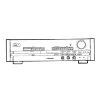
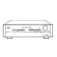
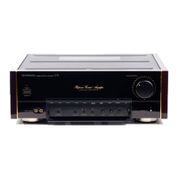
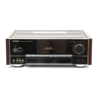
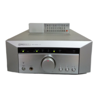
Details on controls like Power, Volume, Muting, Input Selector, Adaptor, and Balance.

Front Panel Operation Switches

Explanation of switches for tape copying, filters, phono selection, mode, tone, and loudness.

Rear Panel Terminals and Outlets

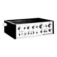
Details on rear panel connections for components, tape decks, and AC power outlets.

Operations

Playing Back Connected Components

Step-by-step guide on how to turn on the unit and select components for playback.

Audio Enhancement Features

Instructions for using Subsonic Filter, High Filter, Tone Controls, and Adaptor Switch for sound adjustment.

Recording and Tape Copying

Procedures for recording audio and copying tapes using connected tape decks.

Surround Sound System Expansion

Guide for connecting and operating a surround processor for enhanced audio experience.

Graphic Equalizer Integration

Instructions for connecting and operating a graphic equalizer for tone quality adjustment.

Troubleshooting

Troubleshooting Common Issues

Guidance on diagnosing and resolving common operational problems and malfunctions.

Specifications

Technical Specifications

Detailed technical data including power, distortion, frequency response, impedance, and dimensions.

Installation Precautions

Recommendations for safe and optimal installation to ensure sound quality and unit longevity.

Related product manuals